SSD1606 e-Paper display driver
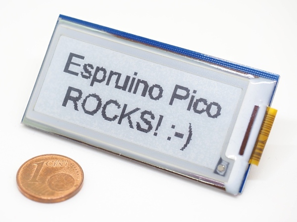
SSD1606 SSD1606 is a CMOS active matrix bistable display driver with controller, that can support a maximum display resolution 128x180. It is used e.g. with e-paper or e-ink displays like the GDE021A1 (shown above) with a resolution of 177x72.
Because of the needed power supply with 2.4 to 3.3V and a typical operating current of 8mA, it is a perfect match for the Espruino Pico. You can even drive it from one of the GPIO pins (they provide up to 20mA current).
Functionality is provided by the SSD1606 (About Modules) module, using the Graphics library.
Notes
- The display can be read perfectly in harsh sunlight, but has no backlighting.
- E-paper displays are not known for fast refresh cycles.
- E-paper displays need only power for updating the display, not for keeping it up.
Wiring Up
The bare display and controller module needs to be connected with a 24pin FPC connector with 0.5mm pitch and an additional driving circuit. There are rather huge and expensive ready to use development boards available from the display manufacturer. You can even try to build the minimum circuit yourself, e.g. like Jaroslav Sýkora did.
The following infos apply only to the connection between SSD1606 and a microcontroller, ignoring the driving circuit.
Pin overview
| SSD1606 | Notes |
|---|---|
| GND | Ground |
| SDA | SPI mosi pin. The SSD1606 provides no miso pin. |
| SCL | SPI Clock pin |
| CS1 | Chip select pin, is used to prepare the SSD1606 to receive data over SPI. Pull High before you send data over SPI. |
| D/C | Data/Command control pin, is used to prepare the SSD1606 to receive either commands (pulled LOW) or data (pulled HIGH) over SPI. |
| Res | Hardware Reset pin, pull LOW to reset the SSD1606. |
| BU | This pin is Busy state output pin When Busy is High, the operation of the chip should not be interrupted, command should not be sent. |
| BS1 | Pin for selecting SPI wire mode, pull LOW for 4-wire mode and HIGH for 3-wire mode. |
| 3.3v | Power pin. |
The SSD1606 provides two types of SPI interface modes, but the module supports 4-wire mode only.
SPI-Mode 4-wire
In 4-wire mode you need to set the D/C pin before each SPI send to signal either a command or data will be send. The module takes care of that for you.
Wiring example for SPI 4-wire mode
| SSD1606 | Espruino Pico | Notes |
|---|---|---|
| GND | GND | |
| SDA | B5 | B5 is SPI-1 mosi on Espruino Pico, you can also use SPI-2 or SPI-3. |
| SCL | B3 | B3 is SPI-1 clock on Espruino Pico, you can also use SPI-2 or SPI-3. |
| CS1 | B6 | You can use any of the GPIO pins on the Espruino Pico. |
| D/C | B7 | You can use any of the GPIO pins on the Espruino Pico. |
| Res | A5 | You can use any of the GPIO pins on the Espruino Pico. |
| BU | A8 | You can use any of the GPIO pins on the Espruino Pico. |
| BS1 | A6 | You can use any of the GPIO pins on the Espruino Pico or connect it to either GND or 3.3v. |
| 3.3v | A7 | You can use any of the GPIO pins on the Espruino Pico to have full control or connect it to 3.3v. |
Software
Example
// per default turn display off
digitalWrite(A7, LOW);

// run following code onInit
E.on('init', function() {
  // SPI configuration
  var spi = SPI1;
  spi.setup({
    mosi: B5,
    sck:  B3
  });
  // create display instance
  var display = require('SSD1606').connect({
    displayType: 'GDE021A1',
    spi        : spi,
    cs1Pin     : B6,
    dcPin      : B7,
    resetPin   : A5,
    busyPin    : A8,
    bs1Pin     : A6, // optional, but if not provided, you need to set the correct SPI mode 4-wire by yourself
    powerPin   : A7  // optional, just do not use the on() or off() function if you do not provide it
  });
  // activate the power to run the display, just a comfort function,
  // you can control the power by yourself as well
  display.on();
  display.hwReset(function(){
    display.init(
      function(err){
        // (optional) fill the internal buffer for all pixels with color white,
        // without this the default color will be black
        display.g.clear(0xFF);
        // not optional - rotate the display x and y coordinates 90 degrees to the right
        display.g.setRotation(1);
        // from here it shows the normal usage
        // set color black for subsequent uses
        display.g.setColor(0x00);
        // set fontsize, see Graphics and Fonts modules for further options
        display.g.setFontVector(20);
        display.g.drawString('Hello World!', 22, 22);
        // from here it shows the needed part
        // (needed) copy internal buffer to display buffer
        display.g.flip();
        // run the display update
        display.refreshScreen(function(err){
          // do whatever you like here, e.g. turn it off when the update is done
          // again just a comfort function
          display.off();
        });
      },
      // clearScreenColor is optional, but prevents e-paper ghosting
      // shadow of an image may be visible after refreshing (only) parts of the screen
      { clearScreenColor: 0x00 }
    );
  });
});
This code will only start after sending it to the Pico and run the save(); command on the left side of web ide.
Double Buffer
This module uses a double buffer, which means you need to call display.g.flip() before any changes take effect.
Rotation
The software example uses display.g.setRotation(1); which is needed for a proper function at least for the GDE021A1 display.
It might be possible to work around this with fiddling around with the gate scanning mechanism (see specification). Right now this seems to be the easiest solution.
Colors
Default background color
The Graphics library is used with a buffer in this module.
Per default all pixels in this buffer have their color set to 0. For the SSD1606 this means black. To adjust the buffer default values, a clear(color) function is provided, use as:
 display.hwReset(function(){
    display.init(function(err){
      // fill the internal buffer for all pixels with one color
      display.g.clear(0xFF);

      // copy internal buffer to display buffer
      display.g.flip();

      // run the display update
      display.refreshScreen(function(err){
        // and turn it off when the update is done
        display.off();
      });
    });
  });
Color values
| Color | Values for using with clear() |
Values for using with setColor() or for for the clearScreenColor option |
|---|---|---|
| white | decimal 255, or hexadecimal 0xFF |
decimal 3 or hexadecimal 0x03 |
| light grey | decimal 85, or hexadecimal 0xAA |
decimal 2 or hexadecimal 0x02 |
| dark grey | decimal 255, or hexadecimal 0x55 |
decimal 1 or hexadecimal 0x01 |
| black | decimal 0, or hexadecimal 0x00 |
decimal 0 or hexadecimal 0x00 |
Pixel Colors under the hood
The display works with an internal ram which maps 1 Byte to 4 Pixels.
| Pixel 1 | Pixel 2 | Pixel 3 | Pixel 4 |
|---|---|---|---|
| Bit 7-6 | Bit 5-4 | Bit 3-2 | Bit 1-0 |
This reverse order of pixels to concrete bits is taken care of by the module with a suitable Graphics configuration.
Graphics.createArrayBuffer(
            displaySizeX,
            displaySizeY,
            bpp,
            {msb: true} // this does the magic for the reverse part
);
The clear() function works with setting a complete byte for 4 pixels at once. All other function set individual pixels.
Pin Configurations
For the module to work you need to provide:
displayType, right now onlyGDE021A1is supportedresetPindcPinbusyPincs1Pin- a configured SPI without miso pin.
Notes on the optional power pin
If you do not provide a power pin, the on(); and off(); functions do not work.
Notes for the optional bs1 pin
The module can set the SPI wire mode independently for you, just provide the BS1 pin.
Example with provided BS1 pin:
  var display = require('SSD1606').connect({
    // other configurations
    dcPin      : a Espruino GPIO pin,
    bs1Pin     : a Espruino GPIO pin
  });
Example without provided BS1 pin, D/C pin is still needed:
  var display = require('SSD1606').connect({
    // other configurations
    dcPin      : a Espruino GPIO pin
  });
Display Configuration
This module needs a concrete display configuration. For the GDE021A1 display the configuration is provided, just set the proper display type as GDE021A1.
  var display = require('SSD1606').connect({
    displayType: 'GDE021A1',
    ... other configrations
  });
If you want to use another display, you can provide its configuration with:
  var display = require('SSD1606').connect({
    display: {
      bpp               : 1 or 2,
      displaySizeX      : up to 128,
      displaySizeY      : up to 180,
      lutRegisterData   : new Uint8Array([LUT Register data 90 bytes provided by display manufacturer]),
      maxScreenBytes    : up to 5580,
      ramXStartAddress  : 0x00,
      ramXEndAddress    : adequate for displaySizeX,
      ramYStartAddress  : 0x00,
      ramYEndAddress    : adequate for displaySizeY
    },
    ... other configrations
  });
It would be really nice if you provide configurations for other displays to all module users, either with creating a pull request(see writing or changing Modules) or posting to the Espruino Forum for Interfacing.
Optional Configurations
Different displays might need different times for refreshing the display and for the hardware reset. You can overwrite the defaults (right now 100ms each).
  var display = require('SSD1606').connect({
    ... the other config
    clearScreenTimeOut: time in ms,
    hardwareResetTimeOut: time in ms
  });
Further Informations
- All SSD1606 commands are documented inside the module, look for the documentation on the
scfunction. - Specification for the usage of the busy pin differ between GDE021A1 and SSD1606 documents. The Javascript module is modelled after the SSD1606 spefication.
Using
(No tutorials are available yet)
Buying
The display and controller combinations are avaible on many online shops, e.g. ebay.com.
For the GDE021A1 ready to use modules including the driving circuit are available at:
Note for german users: be aware of customs charges.
Reference
// Sets registers to power-on values (not needed by default)
SSD1606.prototype.reset = function () { ... }

/* Power on the display, using the provided powerPin.
 */
SSD1606.prototype.on = function () { ... }

/* Power off the display, using the provided powerPin.
 */
SSD1606.prototype.off = function () { ... }

/* Use resetPin to make a hardware reset.
 * @param {Function} callback - callback function
 */
SSD1606.prototype.hwReset = function (callback) { ... }

/* Initialize display.
 * If set it uses the provided bs1Pin to configure the SPI mode between to use 4 lines.
 * Initializing sequence:
 * <ol>
 * <li>Exit deep sleep mode</li>
 * <li>Set data entry mode -  0000 0011 means AM=0 means 'x-mode' and ID=11 means 'x:increment and y:increment'</li>
 * <li>Set RAM X start and end addresses</li>
 * <li>Set RAM Y start and end addresses</li>
 * <li>Set RAM X counter</li>
 * <li>Set RAM Y counter</li>
 * <li>Set booster feedback selection</li>
 * <li>Set display update sequence option - enable sequence: clk -> CP</li>
 * <li>Write LUT register</li>
 * <li>Write VCOM register</li>
 * <li>Set border waveform control</li>
 * <li>Set display update sequence option - enable sequence: clk -> CP -> LUT -> initial display -> pattern display</li>
 * </ol>
 * @param {Object} options - provided options, useBs1Pin and clearScreenColor
 * @param {Function} callback - callback function
 */
SSD1606.prototype.init = function (callback, options) { ... }

/* Send a command to the display, uses the cs1Pin (chip select).
 * Uses the dcPin if spimode is set to 4-lines, otherwise add a bit to the
 * left to signal a command.
 * Possible commands:
 * <ol>
 * <li>0x01 - Driver output control</li>
 * <li>0x02 - Reserve</li>
 * <li>0x03 - Gate driving voltage control</li>
 * <li>0x04 - Source driving voltage control</li>
 * <li>0x05 - Reserve</li>
 * <li>0x06 - Reserve</li>
 * <li>0x07 - Display control</li>
 * <li>0x08 - Reserve</li>
 * <li>0x09 - Reserve</li>
 * <li>0x0A - Reserve</li>
 * <li>0x0B - Gate and source non overlap period control</li>
 * <li>0x0C - Reserve</li>
 * <li>0x0D - Reserve</li>
 * <li>0x0E - Reserve</li>
 * <li>0x0F - Gate scan start position</li>
 * <li>0x10 - Deep sleep mode</li>
 * <li>0x11 - Data entry mode setting</li>
 * <li>0x12 - Software reset</li>
 * <li>0x13 - Reserve</li>
 * <li>0x14 - Reserve</li>
 * <li>0x15 - Reserve</li>
 * <li>0x16 - Reserve</li>
 * <li>0x17 - Reserve</li>
 * <li>0x18 - Reserve</li>
 * <li>0x19 - Reserve</li>
 * <li>0x1A - Write to temperature register</li>
 * <li>0x1B - Read to temperature register</li>
 * <li>0x1C - Write command to temperature sensor</li>
 * <li>0x1D - Load temperature register with temperature sensor reading</li>
 * <li>0x1E - Reserve</li>
 * <li>0x1F - Reserve</li>
 * <li>0x20 - Master acvitvation</li>
 * <li>0x21 - Display update 1</li>
 * <li>0x22 - Display update 2</li>
 * <li>0x23 - Reserve</li>
 * <li>0x24 - Write RAM</li>
 * <li>0x25 - Read RAM</li>
 * <li>0x26 - Reserve</li>
 * <li>0x27 - Reserve</li>
 * <li>0x28 - VCOM sense</li>
 * <li>0x29 - VCOM sense duration</li>
 * <li>0x2A - Program VCOM OTP</li>
 * <li>0x2B - Reserve</li>
 * <li>0x2C - Write VCOM register</li>
 * <li>0x2D - Read OTP Register</li>
 * <li>0x2E - Reserve</li>
 * <li>0x2F - Reserve</li>
 * <li>0x30 - Program WS OTP</li>
 * <li>0x31 - Reserve</li>
 * <li>0x32 - Write LUT register</li>
 * <li>0x33 - Read LUT register</li>
 * <li>0x34 - Reserve</li>
 * <li>0x35 - Reserve</li>
 * <li>0x36 - Program OTP selection</li>
 * <li>0x37 - OTP selection control</li>
 * <li>0x38 - Reserve</li>
 * <li>0x39 - Reserve</li>
 * <li>0x3A - Set dummy line period</li>
 * <li>0x3B - Set gate line width</li>
 * <li>0x3C - Border waveform control</li>
 * <li>0x3D - Reserve</li>
 * <li>0x3E - Reserve</li>
 * <li>0x3F - Reserve</li>
 * <li>0x40 - Reserve</li>
 * <li>0x41 - Reserve</li>
 * <li>0x42 - Reserve</li>
 * <li>0x43 - Reserve</li>
 * <li>0x44 - Set RAM X address position</li>
 * <li>0x45 - Set RAM Y address position</li>
 * <li>0x46 - Reserve</li>
 * <li>0x47 - Reserve</li>
 * <li>0x48 - Reserve</li>
 * <li>0x49 - Reserve</li>
 * <li>0x4A - Reserve</li>
 * <li>0x4B - Reserve</li>
 * <li>0x4C - Reserve</li>
 * <li>0x4D - Reserve</li>
 * <li>0x4E - Set RAM X address counter</li>
 * <li>0x4F - Set RAM Y address counter</li>
 * <li>0xF0 - Booster feedback selection</li>
 * <li>0xFF - no operation NOP</li>
 * </ol>
 * @param {number} command - a command
 */
SSD1606.prototype.sc = function (command) { ... }

/* Prepare send data, prepares the controller to receive data.
 */
SSD1606.prototype.psd = function () { ... }

/* Send data to the controller.
 * @param data - the data
 */
SSD1606.prototype.sd = function (data) { ... }

/* Send command and data to the controller.
 * @param command - the command
 * @param data - the data
 */
SSD1606.prototype.scd = function (command, data) { ... }

/* Checks the busyPin and runs the callback, wenn the busyPin is LOW.
 * @param {Function} callback - the callback function
 */
SSD1606.prototype.cbp = function (callback) { ... }

/* Clears the display screenbuffer with desired color.
 * Possible color values:
 * <ul>
 * <li>parseInt("00000000",2) = all black, or decimal 0, or hexadecimal 0x00</li>
 * <li>parseInt("01010101",2) = dark gray, or decimal 85, or hexadecimal 0x55</li>
 * <li>parseInt("10101010",2) = light gray, or decimal 170, or hexadecimal 0xAA</li>
 * <li>parseInt("11111111",2) = light gray, or decimal 255, or hexadecimal 0xFF</li>
 * </ul>
 * Right now it sends each 4-pixel byte individually, but does not need an
 * internal buffer array.
 * The display driver handles the X and Y RAM counters itself, so it is save to
 * just write the bytes.
 * To leave the write RAM mode a 'NOP' command is sent.
 * According to specification a check of the BusyPin is needed, but this does not work here.
 * It seems the display driver encapsulates this behaviour.
 * @param {Function} callback - the callback function, will be called, when finished
 * @param {number} clearScreenColor - the color to set
 */
SSD1606.prototype.csb = function (callback, clearScreenColor) { ... }

/* Refresh the screen, need to be called by application every time the screen changed.
 * Refresh sequence:
 * <ol>
 * <li>Master activation</li>
 * <li>Display update 2 - part of <em>closebump</em> in specification</li>
 * <li>Master activation  - part of <em>closebump</em> in specification</li>
 * <li>check BusyPin before the display can receive further commands or data. Part of <em>closebump</em> in specification</li>
 * </ol>
 * @param {Function} callback - callback is called, when busy pin is ready.
 */
SSD1606.prototype.refreshScreen = function (callback) { ... }

/* Sets the X and Y RAM counter.
 * @param {number} xCount - X RAM counter
 * @param {number} yCount - Y RAM counter
 */
SSD1606.prototype.sxyc = function (xCount, yCount) { ... }

/* Creates the Graphics object with Graphics.createArrayBuffer(...).
 * Sets the display x size, y size, bits per pixel and msb:true.
 * Provides a clear function to fill in-memory buffer with one color for each pixel.
 * Provides a flip function to flush in-memory buffer to display buffer.
 */
SSD1606.prototype.grfx = function () { ... }

/* Export the module.
 */
exports.connect = function (options) { ... }
This page is auto-generated from GitHub. If you see any mistakes or have suggestions, please let us know.