Arduino Pico adaptor board
There is now an Arduino adaptor shield that converts the Espruino Pico into an Arduino form factor. It is available as part of the Shim Collection
Check out some of the Arduino Shields you can use with this adaptor.
Wiring
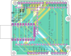
Simply solder an unpinned Espruino Pico flat onto the board (it should be soldered onto the side that contains the silkscreen).
You can solder a Pinned Pico flat by carefully removing the black plastic on the pins first, or you can solder just the 0.1" pins (however you will miss out on some connections - see below).
There is also room for a JST surface mount battery connector, just to the side of the Pico.
The two sets of surface mount pads by the JST connector are for 0805-size 4.7k resistors, which act as pullups for the I2C pins.
Software
The Pin mapping is as follows:
| Arduino | Pico |
|---|---|
| A0 | A0 (on 0.05" pins) |
| A1 | A1 (on 0.05" pins) |
| A2 | A2 (on 0.05" pins) |
| A3 | A3 (on 0.05" pins) |
| A4 | A4 (on 0.05" pins) |
| A5 | A5 |
| D0 | B7 |
| D1 | B6 |
| D2 | B1 |
| D3 | B3 |
| D4 | B4 |
| D5 | B5 |
| D6 | A6 |
| D7 | A7 |
| D8 | A8 |
| D9 | B10 |
| D10 | A10 (on 0.05" pins) |
| D11 | B15 |
| D12 | B14 |
| D13 | B13 |
| SCL | B8 (on 0.05" pins) |
| SDA | B9 (on 0.05" pins) |
However to make this easier we've made a module that contains the pin mapping. You can do:
var ard = require("ArduinoPico");
// use normal arduino-style functions
digitalWrite(ard.D9, 1);
console.log(analogRead(ard.A0));
// or access pins directly
ard.D10.set();
If you're plugging this board into a Seeed Grove kit, you can also use the GroveArduinoPico module to get the correct pins.
Buying
You can:
This page is auto-generated from GitHub. If you see any mistakes or have suggestions, please let us know.