MAG3110 3-axis magnetometer
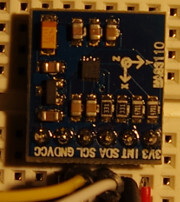
The MAG3110 from NXP/Freescale is a small, low-power, digital 3-axis magnetometer with a wide dynamic range to allow operation in PCBs with high extraneous magnetic fields. The MAG3110:
- Features a standard I2C serial interface.
- is capable of measuring local magnetic fields up to 10 Gauss with output data rates up to 80 Hz (12.5ms).
- Measures the components of the local magnetic field, the sum of the geomagnetic field and the magnetic field created by components on the circuit board
- Can be used in conjunction with a 3-axis accelerometer so that orientation-independent accurate compass heading information may be achieved
The sensor is build into the BBC micro:bit.
Use the MAG3110 (About Modules) module for it.
Wiring
You can use any I2C port, e.g. I2C1:
| Device Pin | Espruino | |
|---|---|---|
| GND | GND | |
| VCC | 3.3 | |
| SDA | B7 | Don't forget I²C pullup if not available on the breakout. |
| SCL | B6 | Don't forget I²C pullup if not available on the breakout. |
| INT | A8 | Any input pin (connection not required), see section Timing |
It's not required to connect INT but is useful if you want to be notified when a new measurement value is available. A transition from 0 to 1 indicates the presence of new measurement data.
Usecases
Initialisiation
I2C1.setup( { scl: B6, sda: B7 } );
var mag = require('MAG3110').connect( I2C1 );
There exists a similar sensor with a different part number FXMS3110CDR1 with different I2C slave address 0x0f
I2C1.setup( { scl: B6, sda: B7 } );
var mag = require('MAG3110').connect( I2C1, { address: 0x0f } );
Operation Modes
MAG3110 supports three operation modes:
- 0 → Standby … very less power consumption; no measuring, but last measurement still readable
- 1 → Active (RAW data) … measuring and getting the raw sensor values
- 2 → Active (Offset-corrected data) … measuring and reading the raw sensor values subtracted be a previously configured offset
I2C1.setup( { scl: B6, sda: B7 } );
var mag = require('MAG3110').connect( I2C1 );
console.log( mag.getMode() ); // outputs 0 = standby (default after power-up)
mag.setMode( 1 ); // bring sensor in Active/Raw-mode → sensor begins to measure
console.log( mag.getMode() ); // outputs 1 (active/raw)
Reading magnetic value
I2C1.setup( { scl: B6, sda: B7 } );
var mag = require('MAG3110').connect( I2C1 );

// We are in standby mode → read() will return always the same value.
console.log( mag.read() ); // outputs { "x": 0, "y": 0, "z": 0 }
console.log( mag.read() ); // outputs { "x": 0, "y": 0, "z": 0 }

// Switching to raw mode → Rotating the sensor position will result in different measurement.
mag.setMode( 1 );
console.log( mag.read() ); // outputs { "x": -130, "y": 346, "z": 743 }
console.log( mag.read() ); // outputs { "x": -125, "y": 334, "z": 735 }

// Offset-corrected mode will return nearly the same result because didn't configured any offset.
mag.setMode( 2 );
console.log( mag.read() ); // outputs { "x": -123, "y": 341, "z": 730 }
Using offset-corrected mode
I2C1.setup( { scl: B6, sda: B7 } );
var mag = require('MAG3110').connect( I2C1 );

// Configuring offset is only possible in standby mode!
mag.setOffset( { x : -123, y: 341, z: 730 } );
mag.setMode( 2 ); // offset-corrected mode

console.log( mag.read() ); // outputs { "x": -2, "y": 6, "z": 3 }

// For comparison
mag.setMode( 1 ); // raw mode
console.log( mag.read() ); // outputs { "x": -125, "y": 341, "z": 735 }
Measuring in standby mode
The sensor is not measuring in standby mode but you can trigger one explicit measurment cycle in standby mode.
I2C1.setup( { scl: B6, sda: B7 } );
var mag = require('MAG3110').connect( I2C1 );

// We are in standby mode after POR, otherwise use setMode(0)
console.log( mag.read() );    // outputs { "x": 0, "y": 0, "z": 0 }

mag.triggerMeasurement();
console.log( mag.read() );    // outputs { "x": -123, "y": 346, "z": 726 }
console.log( mag.getMode() ); // 0 - We are still in standby mode.
Customize sampling parameters
The sensor can work with different ADC Rate. More ADC Rate means higher power consumption but higher output rate. The Over Sample Ratio is the number of samples which will be averaged before a new measurement is available.
| Sampling | Output Rate | Over Sample Ratio | Current |
|---|---|---|---|
| 0 | 80.00 Hz | 16 | 900.0 µA |
| 1 | 40.00 Hz | 32 | 900.0 µA |
| 2 | 20.00 Hz | 64 | 900.0 µA |
| 3 | 10.00 Hz | 128 | 900.0 µA |
| 4 | 40.00 Hz | 16 | 550.0 µA |
| 5 | 20.00 Hz | 32 | 550.0 µA |
| 6 | 10.00 Hz | 64 | 550.0 µA |
| 7 | 5.00 Hz | 128 | 550.0 µA |
| 8 | 20.00 Hz | 16 | 275.0 µA |
| 9 | 10.00 Hz | 32 | 275.0 µA |
| 10 | 5.00 Hz | 64 | 275.0 µA |
| 11 | 2.50 Hz | 128 | 275.0 µA |
| 12 | 10.00 Hz | 16 | 137.5 µA |
| 13 | 5.00 Hz | 32 | 137.5 µA |
| 14 | 2.50 Hz | 64 | 137.5 µA |
| 15 | 1.25 Hz | 128 | 137.5 µA |
| 16 | 5.00 Hz | 16 | 68.8 µA |
| 17 | 2.50 Hz | 32 | 68.8 µA |
| 18 | 1.25 Hz | 64 | 68.8 µA |
| 19 | 0.63 Hz | 128 | 68.8 µA |
| 20 | 2.50 Hz | 16 | 34.4 µA |
| 21 | 1.25 Hz | 32 | 34.4 µA |
| 22 | 0.63 Hz | 64 | 34.4 µA |
| 23 | 0.31 Hz | 128 | 34.4 µA |
| 24 | 1.25 Hz | 16 | 17.2 µA |
| 25 | 0.63 Hz | 32 | 17.2 µA |
| 26 | 0.31 Hz | 64 | 17.2 µA |
| 27 | 0.16 Hz | 128 | 17.2 µA |
| 28 | 0.63 Hz | 16 | 8.6 µA |
| 29 | 0.31 Hz | 32 | 8.6 µA |
| 30 | 0.16 Hz | 64 | 8.6 µA |
| 31 | 0.08 Hz | 128 | 8.6 µA |
I2C1.setup( { scl: B6, sda: B7 } );
var mag = require('MAG3110').connect( I2C1 );

// Default is sample = 0
console.log( mag.getSamplingParams() ); // → 0

mag.setSamplingParams( 11 ); // 4 Measurements per second
console.log( mag.getSamplingParams() ); // → 11

mag.read(); // Over Sample Ratio = 128 → Results are smoother.
Timing
It's alway possible to read the last measured data but sometimes you want to know whether new data is available or not.
I2C1.setup( { scl: B6, sda: B7 } );
var mag = require('MAG3110').connect( I2C1 );

mag.setMode( 0 ); // standby mode
mag.setSamplingParams( 31 ); // low power consumption (8.6µA) but 12 seconds (0.08 Hz) per measurement

console.log( mag.isNewDataAvailable() ); // → false
mag.setMode(1); // raw mode + start measuring
var start = getTime();
setInterval( function() {
    if (mag.isNewDataAvailable()) {
        mag.read(); // reading the measurement will reset the "new data available" flag
        console.log( "New data available after " + (getTime()-start).toFixed(1) + " seconds" );
    }
}, 300 );
This program snippet will output:
New data available after 1.8 seconds
New data available after 13.5 seconds
New data available after 25.2 seconds
New data available after 36.9 seconds
New data available after 48.6 seconds
Bug? The first availability after 1.8 seconds looks like a sensor bug. Maybe NXP/Freescale can explain the behavior?
Instead of pooling you can use the INT pin to detect new data. Assuming INT is connected with A8 the same program looks like:
I2C1.setup( { scl: B6, sda: B7 } );
var mag = require('MAG3110').connect( I2C1 );

mag.setMode( 0 ); // standby mode
mag.setSamplingParams( 31 ); // low power consumption (8.6µA) but 12 seconds (0.08 Hz) per measurement

console.log( mag.isNewDataAvailable() ); // → false
mag.setMode(1); // raw mode + start measuring
var start = getTime();

setWatch( function() {
    mag.read(); // reading the measurement will reset the "new data available" flag
    console.log( "New data available after " + (getTime()-start).toFixed(1) + " seconds" );
}, A8, { repeat: true, edge: 'rising' } );
A transition from 0 to 1 on INT indicates the presence of new measurement data.
Magnetic Reset
A magnetic reset is required after exposure to an excessive magnetic field which exceeds the Full Scale Range of +/-1000µT, e.g. near a speaker magnet. There are two possibilities: manual magnetic sensor reset (One-Shot) or automatic magnetic reset before each data acquisition.
I2C1.setup( { scl: B6, sda: B7 } );
var mag = require('MAG3110').connect( I2C1 );
mag.magneticReset(); // one manual magnetic reset after por
Another option is to enable automatic magentic sensor reset:
I2C1.setup( { scl: B6, sda: B7 } );
var mag = require('MAG3110').connect( I2C1 );
mag.setAutomaticMagneticReset( true );
Measuring Temperature
It's possible to measure the dia temperature of the MAG3110. This is used internally for removing temperature dependency. The sensitivity of the temperature is 1°C/LSB but the offset is not factory trimmed, e.g. my sensor say -7°C while 21°C in reality.
I2C1.setup( { scl: B6, sda: B7 } );
var mag = require('MAG3110').connect( I2C1 );
mag.setMode( 1 ); // Measuring only works in the active modes - also for temperature

console.log( "Temperature = " + mag.readTemperature() + " °C" ); // → -7 °C
Buying
Links
Alternatives
Reference
/* Read the current operation mode from the sensor
 * The sensor is in standby operation mode after power on reset.
 * 0 .. standby
 * 1 .. active (RAW data)
 * 2 .. active (offset-corrected data)
 * @returns {number}
 */
MAG3110.prototype.getMode = function () { ... }

/* Write the new operation mode to the sensor.
 * If you change into an active mode (raw or offset-corrected) then the automatic magnetic sensor reset will be disabled.
 * You have to enable this flag by calling setAutomaticMagneticReset(true) if required.
 * @param mode new operation mode
 *  0 .. standby
 *  1 .. active (RAW data)
 *  2 .. active (offset-corrected data)
 */
MAG3110.prototype.setMode = function (mode) { ... }

/* Read the last measurement value from the sensor
 * The complements x,y and z from the different axis are in the range of
 * -30000 to +30000.
 * If the operation mode is 2 (active/offset-corrected data) the result
 * is the raw sensor data minus the configured offset.
 * If the operation mode is 1 (active/raw data) the configured offset will be ignored.
 * @returns {{x: number, y: number, z: number}}
 */
MAG3110.prototype.read = function () { ... }

/* Read the user offsets of the x-,y- and z-axis which are automatically subtracted
 * by the MAG3110 if the sensor is in active-mode with offset-corrected data (mode = 2).
 * Possible values are in the range from -10000 to +10000.
 * After POR all values are 0.
 * @returns {{x: number, y: number, z: number}} offset vector
 */
MAG3110.prototype.getOffset = function () { ... }

/* Write new user offsets of the x, y and z-axis into the sensor
 * The values are not persistent (no EEPROM) and are lost after power down.
 * @param offset {{x: number, y: number, z: number}} new offset vector
 */
MAG3110.prototype.setOffset = function (offset) { ... }

/* Starts one measurement in standby operation mode.
 * In standby mode triggered measurement will occur immediately and part will return to standby mode
 * as soon as the measurement is complete. The method can only be call in standby operation mode.
 * The sampling parameters will be set to 0 (max. OutputRate).
 */
MAG3110.prototype.triggerMeasurement = function () { ... }

/* Returns whether a new measurement available
 * @returns {boolean}
 */
MAG3110.prototype.isNewDataAvailable = function () { ... }

/* Change the over-sampling ratio and the data rate of the sensor. Possible values are  in the range from 0 to 31.
 * 0: OutputRate: 80.00 Hz, Over Sample Ratio: 16, ADC Rate: 1280 Hz, Current: 900µA
 * 1: OutputRate: 40.00 Hz, ...
 * @param sampling Parameter index in the range from 0 to 31.
 */
MAG3110.prototype.setSamplingParams = function (sampling) { ... }

/* Read the configured over-sampling ratio and data rate
 * Possible values are in the range 0 to 31.
 * See setSamplingParams(..) for more details.
 * @returns {number}
 */
MAG3110.prototype.getSamplingParams = function () { ... }

/* Read the die temperature in °C in the range from -40°C to 125°C.
 * The temperature data is updated on every measurement cycle.
 * The sensitivity of the temperature sensor is factory trimmed to 1°C but the absolute offset is NOT calibrated.
 * It must be calibrated by the user software if absolute accuracy is required.
 * @returns {number} temperatur in °C
 */
MAG3110.prototype.readTemperature = function () { ... }

/* Performs a manual magnetic sensor reset (One-Shot).
 * Initiates a magnetic sensor reset cycle that will restore correct operation after exposure to an excessive magnetic
 * field wich exceeds the Full Scale Range of +/-1000µT, e.g. near a speaker magnet.
 */
MAG3110.prototype.magneticReset = function () { ... }

/* Set the automatic magentic reset flag.
 * If set the magnetic resets occur automatically before each data acquisition. If unset no automatic reset occurs.
 * The default value after power on reset is false (no automatic magnetic reset).
 * @param automatic true, if automatic magnetic reset before each measurement
 */
MAG3110.prototype.setAutomaticMagneticReset = function (automatic) { ... }

// Internal API: Read one byte from register reg
MAG3110.prototype.read8 = function (reg) { ... }

// Internal API: Write one byte value to register reg
MAG3110.prototype.write8 = function (reg, value) { ... }

exports.connect = function (i2c, options) { ... }
This page is auto-generated from GitHub. If you see any mistakes or have suggestions, please let us know.