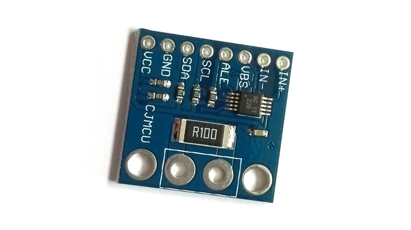
INA226 Current/Voltage Measurement IC
The TI INA226 is a voltage and current monitor designed for voltages up to 36v. In Espruino, the INA226 module (About Modules) can be used to interface to it.
There is also an Espruino module for the INA219.
You can buy (see below) breakout board containing the INA226 along with a shunt resistor pre-wired:

Wiring
| INA226 | Espruino |
|---|---|
| IN+ | Shunt side 1 - DON'T CONNECT TO ESPRUINO |
| IN- | Shunt side 2 - DON'T CONNECT TO ESPRUINO |
| VBS | Voltage being measured - connect to one side of the shunt or the other (depending which voltage you want to measure) |
| ALE | Alert Output (pulled to 0v when data is ready) |
| SCL | I2C SCL - connect to an I2C-cpable pin on Espruino |
| SDA | I2C SDA - connect to an I2C-cpable pin on Espruino |
| GND | Ground |
| VCC | 3.3v Supply voltage |
| A0/A1 | May not be available - I2C address selection |
Usage
Usage is pretty straightforward.
In this example SCL is connected to B3, and SDA is connected to B4 - software I2C
is being used so you could connect using any available pins.
// Setup I2C
var i2c = new I2C();
i2c.setup({sda:B4, scl:B3});
// initialise INA226
var INA226 = require("INA226");
var ina = new INA226(i2c, {
  average:1024, // how many samples to take and average (1024 = about 1 reading a second)
  shunt:0.1, // the shunt resistor's value
  maxCurrent: 10  // max current we expect to measure (the lower this is the more accurate measurements are)
});
// You can now simply read the data
print(ina.read());
/* Outputs something like:
{ "vshunt": 0.024475,
  "vbus": 9.80875,
  "power": 0.23651123046,
  "current": 0.0244140625,
  "overflow": false
}
*/
You can also use the alert pin (connected here to pin B5) to
detect when a conversion has been done and read the data.
pinMode(B5,"input_pullup");
setWatch(function() {
  print(ina.read());
}, B5, {edge:"falling",repeat:true});
Reference
// read reg
INA226.prototype.rd = function (a) { ... }

// write reg
INA226.prototype.wr = function (a, d) { ... }

// read reg signed
INA226.prototype.rds = function (a) { ... }

/* Returns an object with:

* vshunt - voltgage across shunt - -0.082 to 0.082mV
* vbus - bus voltage - 0 to 41v
* power - calculated power in watts
* current - calculated current in amps
* overflow - was there an arithmetic overflow during the averaging?
*/
INA226.prototype.read = function () { ... }

/* addr  = I2C address, default is 0x40 - if A0/A1 are GND
maxCurrent = Largest amount of current expected to be measured (10A default)
shunt = shunt resistance in ohms (default 0.1 Ohms)
average = averaging for a reading (default 256) - 1,4,16,64,128,256,512 or 1024
*/
function (i2c, options) { ... }
Using
(No tutorials are available yet)
Buying
INA226 sensors on breakout boards can be purchased from:
(Other types of TI current sensor, eg. INA219 can also be purchased, but won't directly work with this module)
This page is auto-generated from GitHub. If you see any mistakes or have suggestions, please let us know.