INA219 Zero-Drift, Bidirectional Current/Power Monitor With I2C Interface
The TI INA219 is a voltage and current monitor designed for voltages up to 26v. In Espruino, the INA219 module (About Modules) can be used to interface to it.
There is also an Espruino module for the INA226.
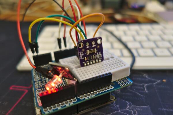
You can buy (see below) breakout board containing the INA219 along with a shunt resistor pre-wired:
Wiring
You can wire this up as follows:
| Device Pin | Espruino |
|---|---|
| GND | GND |
| VCC | 3.3 |
| SCL | I2C SCL - connect to an I2C-capable pin on Espruino |
| SDA | I2C SDA - connect to an I2C-capable pin on Espruino |
Usage
Example usage (using a Pixl.js)
I2C1.setup({ sda: A4, scl: A5 });

const ina219 = require("INA219").connect(I2C1);

console.log(ina219.initDevice());

setInterval(() => {
  g.clear();
  const volts = ina219.getBusMilliVolts() / 1000 + 'V';
  const milliamps = ina219.getBusMicroAmps() * 1000 + 'mA';
  const milliwatts = ina219.getBusMicroWatts() * 1000 + 'mW';

  console.log(volts);
  console.log(milliamps);
  console.log(milliwatts);
  console.log('-----');

  // show on the Pixl.js built-in LCD
  g.drawString(volts, 30, 20);
  g.drawString(milliamps, 30, 30);
  g.drawString(milliwatts, 30, 40);
  g.flip();
}, 1000);
The default maximum expected current is 3.2A and the resistor shunt is 0.1 ohms.
connect() also accepts an options object for its second positional parameter.
This allows you to customize the accuracy of the sensor depending on the shunt
and the maximum current you will be using.
For example:
I2C1.setup({ sda: A4, scl: A5 });

const options = {
  maximumExpectedCurrent: 1, // in amps
  rShunt: 0.1, // in ohms
};
const ina219 = exports.connect(I2C1, options);
Will increase the precision of the measurements in exchange for a lower maximum current that can be measured.
See page 12 of the datasheet for more information.
Reference
INA219.prototype.readWord = function (address) { ... }

INA219.prototype.readSigned = function (address) { ... }

INA219.prototype.writeWord = function (address, data) { ... }

/* initializes the device
 *
 *  initDevice() performs a quick check to see if the device at the I2C address
 *  is actually an INA219.
 *
 *  It will then calculate a calibration factor based on the resistor shunt and
 *  the maximum expected current (passed in as options in the constructor).
 *
 *  returns an object with the calibration factor
*/
INA219.prototype.initDevice = function () { ... }

INA219.prototype.getBusRaw = function () { ... }

// returns the voltage measurement in millivolts
INA219.prototype.getBusMilliVolts = function () { ... }

INA219.prototype.getShuntRaw = function () { ... }

// returns the voltage drop across the shunt in micro volts
INA219.prototype.getShuntMicroVolts = function () { ... }

// returns the current measurement in microamps
INA219.prototype.getBusMicroAmps = function () { ... }

// returns the power measurement in microwatts
INA219.prototype.getBusMicroWatts = function () { ... }

/* returns a new INA219 object with default values (if positional parameters
 *  were not provided)
 *
 *  the defaults are:
 *
 *  const defaultOptions = {
 *    maximumExpectedCurrent: 3.2768, // in amps
 *    rShunt: 0.1, // in ohms
 *  };
*/
exports.connect = function (i2c, options, deviceAddress) { ... }
Using
(No tutorials are available yet)
Buying
INA219 sensors on breakout boards can be purchased from:
This page is auto-generated from GitHub. If you see any mistakes or have suggestions, please let us know.