Espruino WiFi
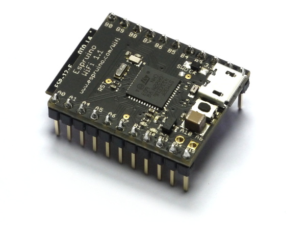
Espruino WiFi is a tiny USB and WiFi-enabled microcontroller that can be programmed in JavaScript
Just plug it into your computer and get started in seconds with the Web IDE - no software installation needed!
Just got your Espruino WiFi? Get started here!
Note: Espruino WiFi provides an easy, well-supported way to get on the Internet, however it's not the only way to access a WiFi network from an Espruino board. See here for more information.
Contents
Features
- 30mm x 23mm (1.2 x 0.9 inch)
- On-board Micro USB connector
- 2 rows of 11 0.1" pins, with 2 extra 0.1" holes
- 21 GPIO pins : 8 Analog inputs, 20 PWM, 1 Serial, 3 SPI, 3 I2C
- Three on-board LEDs (2x user programmable, 1x WiFi activity) and one button.
- STM32F411CEU6 32-bit 100MHz ARM Cortex M4 CPU
- 512kb flash, 128kb RAM
- ESP8266 WiFi (802.11 b/g/n)
- All GPIO is 5 volt tolerant (Arduino compatible)
- RTC with external oscillator
- On-board 3.3v 250mA voltage regulator, accepts voltages from 3.5v to 5v (please see notes under pinout below)
- Current draw in sleep: < 0.05mA - over 2.5 years on a 2500mAh battery
- 500mA polyfuse on board
Note: We did mark the Espruino WiFi as discontinued during the pandemic because of the component shortage, but as parts have become available we have started producing it again.
Pinout
Hover the mouse over a pin function for more information. Clicking in a function will tell you how to use it in Espruino.
- Purple boxes show pins that are used for other functionality on the board. You should avoid using these unless you know that the marked device is not used.
- ! boxes contain extra information about the pin. Hover your mouse over them to see it.
- 3.3v boxes mark pins that are not 5v tolerant (they only take inputs from 0 - 3.3v, not 0 - 5v).
- 3.3 is a 3.3v output from the on-board Voltage regulator.
- GND is ground (0v).
- ADC is an Analog to Digital Converter (for reading analog voltages)
- PWM is for Pulse Width Modulation. This creates analog voltages from a digital output by sending a series of pulses.
- SPI is the 3 wire Serial Peripheral Interface.
- USART is a 2 wire peripheral for Serial Data.
- I2C is the 2 wire Inter-Integrated Circuit bus.
Pins not on connectors
Note: Unlike Espruino Pico and the original Espruino board, Espruno WiFi doesn't contain any
battery switchover circuitry. The +/+VUSB pin is connected straight to USB 5V, and shouldn't be used to power the
WiFi board while Micro USB is plugged in, unless it is via a diode from 5V.
Information
Using WiFi
Connecting to an AP
To use wifi, simply require the Wifi module and call connect. The following code
will connect and then request the page http://www.pur3.co.uk/hello.txt:
var WIFI_NAME = "";
var WIFI_OPTIONS = { password : "" };

var wifi = require("Wifi");
wifi.connect(WIFI_NAME, WIFI_OPTIONS, function(err) {
  if (err) {
    console.log("Connection error: "+err);
    return;
  }
  console.log("Connected!");
  getPage();
});

function getPage() {
  require("http").get("http://www.pur3.co.uk/hello.txt", function(res) {
    console.log("Response: ",res);
    res.on('data', function(d) {
      console.log("--->"+d);
    });
  });
}
For more information on HTTP requests/etc once connected, check out this Page on HTTP.
Note: If you want Espruino to connect at power on after you have
saved, make sure that you call the WiFi initialisation code inside an
onInit function - eg:
var WIFI_NAME = "";
var WIFI_OPTIONS = { password : "" };

var wifi;

function onInit() {
  wifi = require("Wifi");
  wifi.connect(WIFI_NAME, WIFI_OPTIONS, function(err) {
    if (err) {
      console.log("Connection error: "+err);
      return;
    }
    console.log("Connected!");
    getPage();
  });
}
Access Point Mode
Espruino WiFi can be made into a WiFi access point with:
var wifi = require("Wifi");

wifi.startAP('EspruinoAP', { password: '0123456789', authMode: 'wpa2' }, function(err) {
  if (err) throw err;
  console.log("Connected!");
});
See the reference below for more information. startAP and connect can be used together to make Espruino become an access point while also connecting to another WiFi network. In that case, it'll have the DHCP-assigned IP address on the WiFi network it is connected to, and the IP address 192.168.4.1 on the access point it has created.
Note: In 2v06 and earlier, you must specify a dummy password in order to have a 'open' access point, eg. wifi.startAP('EspruinoAP', { password: '0123456789', authMode: 'open' }, .... In 2v07 and later this is fixed, and even just wifi.startAP('EspruinoAP', { }, ... will create an open access point.
WiFi events
You can also be notified on particular WiFi events:
wifi.on('associated',function() { console.log("We're connected to an AP"); });
wifi.on('connected',function() { console.log("We have an IP Address"); });
wifi.on('disconnected',function() { console.log("We disconnected"); });
Reference
On Espruino firmwares version 1v96 and later, WiFi functionality is now
built in via the Wifi module
accessed with require("Wifi").
On earlier (pre-1v96) versions of the Espruino WiFi firmware, WiFi functionality
was implemented with the EspruinoWiFi JS module which is accessed with
require("EspruinoWiFi").
/* Power on the ESP8266 and connect to the access point
      apName is the name of the access point
      options can contain 'password' which is the AP's password
      callback is called when a connection is made
*/
exports.connect = function (apName, options, callback) { ... }

/* Disconnect from the WiFi network and power down the
ESP8266.
*/
exports.disconnect = function (callback) { ... }

/* Create a WiFi access point allowing stations to connect.
     ssid - the AP's SSID
     options.password - the password - must be at least 8 characters (or 10 if all numbers)
     options.authMode - "open", "wpa2", "wpa", "wpa_wpa2"
     options.channel - the channel of the AP
*/
exports.startAP = function (ssid, options, callback) { ... }

/* Stop being an access point and disable the AP operation mode.
   AP mode can be re-enabled by calling startAP.
*/
exports.stopAP = function (callback) { ... }

/* Scan for access points, and call the callback(err, result) with
   an array of {ssid, authMode, rssi, mac, channel}
*/
exports.scan = function (callback) { ... }

/* Get the IP and MAC address when connected to an AP and call
`callback(err, { ip : ..., mac : ...})`. If err isn't null,
it contains a string describing the error. You must be connected to
an access point to be able to call this successfully. For AP mode use getAPIP
*/
exports.getIP = function (callback) { ... }

/* Set WiFi client IP address. Call with
either: wifi.setIP(undefined, callback) // enable DHCP (the default) - can take a few seconds to complete
either: wifi.setIP({ip:"192.168.1.9"}, callback) // disable DHCP, use static IP
or: wifi.setIP({ip:"192.168.1.9", gw:"192.168.1.1", netmask:"255.255.255.0"}, callback) // disable DHCP, use static IP
You must be connected to an access point to be able to call this successfully
*/
exports.setIP = function (settings, callback) { ... }

/* Calls the callback with {ip,gw,netmask,mac} of the WiFi Access Point.
You must be in AP mode with startAP to get useful values returned.
*/
exports.getAPIP = function (callback) { ... }

/* Set WiFi access point details. Call with
either: wifi.setAPIP({ip:"192.168.1.1"}, callback)
or: wifi.setAPIP({ip:"192.168.1.1", gw:"192.168.1.1", netmask:"255.255.255.0"}, callback)
You must be in AP mode with startAP to be able to call this successfully
*/
exports.setAPIP = function (settings, callback) { ... }

// Set the name of the Espruino WiFi's access point (this isn't DNS, this is just the WiFi access point name)
exports.setHostname = function (hostname, callback) { ... }

/* Ping the given address. Callback is called with the ping time
in milliseconds, or undefined if there is an error
*/
exports.ping = function (addr, callback) { ... }

/* Switch to using a higher communication speed with the WiFi module.

* `true` = 921600 baud
* `false` = 115200
* `1843200` (or any number) = use a specific baud rate.
*
eg. `wifi.turbo(true,callback)` or `wifi.turbo(1843200,callback)`
*/
exports.turbo = function (enable, callback) { ... }

// This function returns some of the internal state of the WiFi module, and can be used for debugging
exports.debug = function () { ... }
Tutorials
Tutorials using the Espruino WiFi Board:
") Advanced Debug (SWD)
Advanced Debug (SWD)
 YouTube View Counter
") Quick Start (USB)
Quick Start (USB)
 Building Custom Firmware
 Storing HTTPS Certificates
") Quick Start (Writing Code)
Quick Start (Writing Code)
 Handling POSTed data from Forms
 WiFi Websocket Server
 Home Automation with Raspberry Pi, MQTT, and Espruino
 Logging to Google Sheets
There aren't currently many tutorials specifically for the Espruino WiFi, however it can be used just like the Espruino Pico, which has many more tutorials available:
 Espruino Home Computer
 Arduino Pico adaptor board
 Image Slideshow with ILI9341 display
 Espruino Web IDE
 Pico Buttons
 GNSS Espruino Position Tracker
 Espruino ISS Notifier
 Flappy Bird Game
 Low-level STM32 Peripheral access
 Pico Clock
 Snake Game
 5 Minute Wire Loop Game
 Pico Weather Station
 Pico LCD Display Hello World
 Pico Electronic Dice
 Controlling Pico from a Computer
 AA/AAA Battery Charger
 Interactive Web-based UI
 Slot Machine
 Pico Vibration
 Pico Piano
 Pico Light Sensor
 Pico Infrared Transmit and Receive
 Pico FET Output
Hardware Limitations
- You can only have one watched pin of each number (Watching A0 and A1 is fine, but watching A1 and B1 isn't)
- When in Deep sleep, pin B9 cannot be used as a watch (as A9 is used to wake up on USB)
Troubleshooting
Please see the Troubleshooting section.
Firmware Updates
We'd strongly recommend that you use the Web IDE to update the firmware on this board - please see the Firmware Update page for detailed instructions.
If you do manage to erase all your board's flash memory you can use the on-chip bootloader though - see below.
Advanced Reflashing
In very rare cases (if you are experimenting with writing to Flash Memory), you may be able to damage the bootloader, which will effectively 'brick' the Espruino WiFi.
To fix this, you'll have to use the hard-wired USB DFU (Device Firmware Upgrade) bootloader. You can also use this method for flashing non-Espruino firmwares to Espruino.
Just:
- Short out the
BOOT0/BTNsolder jumper on the back of the board - you can do this by drawing over it with a pencil. - Install ST's DFU utility on Windows, or dfu-util for Mac or Linux
- Download the latest Espruino WiFi binary from espruino.com/binaries
- Hold down the Espruino WiFi's button while plugging it into USB
- Use the DFU tool to flash the firmware. Using the GUI on windows, or with the command
sudo dfu-util -a 0 -s 0x08000000 -D espruino_binary_file.binfordfu-utilon Mac/Linux. - Un-short the
BOOT0/BTNjumper to re-use the original Espruino Bootloader. If you used a Pencil mark then you may need to use cleaning fluid and a small brush to totally clear out the graphite.
Updating ESP8266 firmware
Espruino WiFi contains and ESP8266 module to handle WiFi communications. It ships with firmware 0v40, but it can be updated reasonably easily if needed:
- In the Web IDE, click
Settings,Flasher - Down the bottom of the screen, under
Espruino WiFi Firmwareclick theUpdate WiFi modulebutton to update the firmware. This will take several minutes, but will result in the firmware being updated. - If you are unsure of your currently installed version, you can
click
Check versionto find out what is installed.
Advanced ESP8266 Reflashing
You can also turn your Espruino WiFi's CPU into a USB-serial bridge, allowing you to use your desktop PC to flash the Espruino WiFi.
USE WITH CAUTION: The unmodified esptool.py tool for updating firmware
sends packets of data that are too large, and will not be able to successfully
flash the ESP8266, leaving it bricked.
- First connect to your Espruino WiFi with the Web IDE - make a note of the Espruino
Path (usually
/dev/ttySomethingorCOMxx) that is displayed in the connection screen. - Ensure
Save on Sendmode inCommunicationsettings is set to the default ofTo RAM. - Upload the following code:
// Setup serial
Serial2.setup(74880, { rx: A3, tx : A2 });
// Bridge Serial and USB
Serial2.on('data',d=>USB.write(d));
USB.on('data',d=>Serial2.write(d));
// boot module in bootloader mode
digitalWrite(A14, 0); // make sure WiFi starts off
digitalWrite(A13, 0); // into of boot mode
digitalWrite(A14, 1); // turn on wifi
console.log("Now disconnect the IDE");
LoopbackA.setConsole();
Now Disconnect the Web IDE
Download
esptoolfrom https://github.com/espressif/esptoolCheck out tag
v2.0withgit checkout v2.0Modify
esptool.pyto change bothESP_RAM_BLOCKandFLASH_WRITE_SIZEto0x100Download the ESP8266 1.5.4 firmware (originally from here)
Run the following command. You'll need to replace
/dev/ttyACM0with the device path (see the first step)
./esptool.py --no-stub --port /dev/ttyACM0 --baud 74880 write_flash --flash_mode dio 0 AiThinker_ESP8266_DIO_32M_32M_20160615_V1.5.4.bin
- When complete, unplug the Espruno WiFi and re-plug it
- Now check firmware works with:
// Setup serial
Serial2.setup(74880, { rx: A3, tx : A2 });
// Bridge Serial and USB
Serial2.on('data',d=>USB.write(d));
USB.on('data',d=>Serial2.write(d));
// boot module in bootloader mode
digitalWrite(A14, 0); // make sure WiFi starts off
digitalWrite(A13, 1); // out of boot mode
digitalWrite(A14, 1); // turn on wifi
// Ask for version
setTimeout(_=>{
  Serial2.setup(115200, { rx: A3, tx : A2 });
  Serial2.print("AT+GMR\r\n");
}, 1000);
After a few seconds it should report something like:
>AT+GMR
AT version:1.1.0.0(May 11 2016 18:09:56)
SDK version:1.5.4(baaeaebb)
Ai-Thinker Technology Co. Ltd.
Jun 13 2016 11:29:20
OK
And the firmware is updated!
Other Official Espruino Boards


This page is auto-generated from GitHub. If you see any mistakes or have suggestions, please let us know.