Espruino Pico
Buy Now
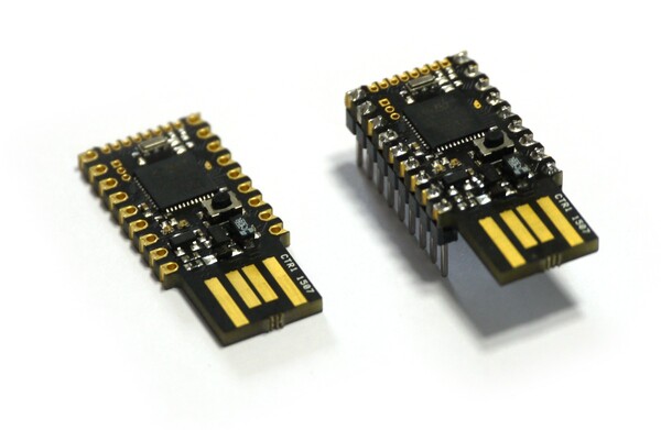
Espruino Pico is a tiny USB-enabled microcontroller that can be programmed in JavaScript
Just plug it into your computer and get started in seconds with the Web IDE - no software installation needed!
Just got your Pico? Get started here!
Contents
Features
- 33mm x 15mm (1.3 x 0.6 inch)
- 22 GPIO pins : 9 Analog inputs, 21 PWM, 2 Serial, 3 SPI, 3 I2C
- All GPIO is 5 volt tolerant (Arduino compatible)
- 2 rows of 9 0.1" pins, with a third 0.05" row of 8 pins on the end
- On-board USB Type A connector
- Two on-board LEDs and one button.
- STM32F401CDU6 32-bit 84MHz ARM Cortex M4 CPU
- 384kb flash, 96kb RAM
- On-board 3.3v 250mA voltage regulator, accepts voltages from 3.5v to 16v
- Current draw in sleep: < 0.05mA - over 2.5 years on a 2500mAh battery
- On-board FET can be used to drive high-current outputs
- Rev 1v4: 500mA polyfuse on board
- Rev 1v4: CE and RoHS certification
Pinout
Hover the mouse over a pin function for more information. Clicking in a function will tell you how to use it in Espruino.
- Purple boxes show pins that are used for other functionality on the board. You should avoid using these unless you know that the marked device is not used.
- ! boxes contain extra information about the pin. Hover your mouse over them to see it.
- 3.3v boxes mark pins that are not 5v tolerant (they only take inputs from 0 - 3.3v, not 0 - 5v).
- 3.3 is a 3.3v output from the on-board Voltage regulator.
- GND is ground (0v).
- VBAT is the battery voltage output (see the Espruino Board Reference).
- ADC is an Analog to Digital Converter (for reading analog voltages)
- PWM is for Pulse Width Modulation. This creates analog voltages from a digital output by sending a series of pulses.
- SPI is the 3 wire Serial Peripheral Interface.
- USART is a 2 wire peripheral for Serial Data.
- I2C is the 2 wire Inter-Integrated Circuit bus.
Note: There is no built-in fuse on the Espruino Pico 1v3 (1v4 contains one). You should check that your circuit does not contain shorts with a volt meter before you plug it into USB, or you may damage your board.
Information
- There's an API reference here
- Circuit Diagram
- Board Layout
- STM32F401CD Datasheet
- STM32F401CD Reference Manual
- Part libraries for Eagle CAD and KiCad
- Part library for Fritzing
Tutorials
Tutorials using the Pico Board:
 Espruino Home Computer
") Advanced Debug (SWD)
Advanced Debug (SWD)
 Arduino Pico adaptor board
 Image Slideshow with ILI9341 display
 Espruino Web IDE
") Quick Start (USB)
Quick Start (USB)
 Pico Buttons
 Storing HTTPS Certificates
 GNSS Espruino Position Tracker
 Espruino ISS Notifier
") Quick Start (Writing Code)
Quick Start (Writing Code)
 Handling POSTed data from Forms
 Flappy Bird Game
 Low-level STM32 Peripheral access
 Pico Clock
 Snake Game
 5 Minute Wire Loop Game
 Pico Weather Station
 Pico LCD Display Hello World
 Pico Electronic Dice
 Controlling Pico from a Computer
 AA/AAA Battery Charger
 Interactive Web-based UI
 Logging to Google Sheets
 Slot Machine
 Pico Vibration
 Pico Piano
 Pico Light Sensor
 Pico Infrared Transmit and Receive
 Pico FET Output
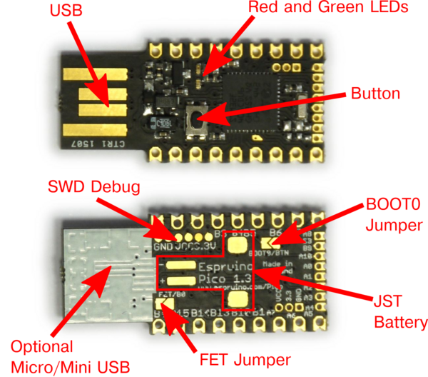
Layout
| Name | Function |
|---|---|
| USB | Printed Type A USB connector plugs straight into standard socket |
| LEDs | Red and Green LEDs accessible using the built-in variables LED1 and LED2 |
| Button | Button accessible using the built-in variable BTN |
| SWD Debug | (Advanced) SWD debug connections for firmware debugging |
| BOOT0 Jumper | (Advanced) Short this jumper out to connect the button to BOOT0. Plugging the device in with the button pressed will the cause the DFU bootloader to be started, allowing you to change absolutely all of Espruino's firmware. |
| JST Battery | Pads for a surface mount JST PHR-2 Battery connector (see below) |
| Micro/Mini USB | Under the white silkscreen are pads to solder USB sockets on (see below) |
| FET Jumper | Shorting this jumper allows the PFET to be controlled from pin B0 (see below) |
Note: The two jumpers can be shorted out just by scribbling over them with an HB pencil.
Embedding the Pico
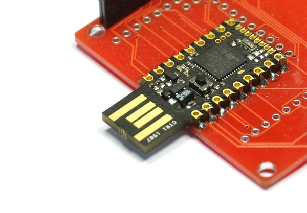
The Pico is designed to be easy to include in your designs. The 0.1" pins are easy to fit in to sockets, and castellated edges mean that unpinned Picos can easily be surface-mounted directly to a PCB.
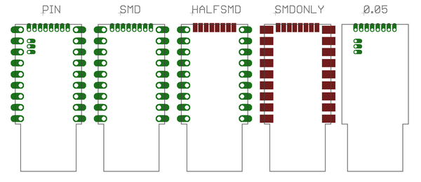
To make it even easier, there are part libraries for Eagle CAD and KiCad. The Eagle CAD library includes the Pico's footprint in several different configurations (KiCad is SMDONLY):
| Library Name | Description |
|---|---|
| PICO_PIN | Through-hole connections for all of the Pico's pins |
| PICO_SMD | Through-hole connections that can also be used to surface-mount a Pico |
| PICO_HALFSMD | 0.1" Through-hole connections, with surface-mount pads for 0.05" pins. This often helps with routing small boards (wires can be run under the 0.05" pads) |
| PICO_SMDONLY | Surface mount-only pads for a Pico. Good for double-sided boards with large SMD components on the other side |
| PICO_0.05 | Through-hole pads for just 0.05" pins (including power) - useful for very small add-on boards |
These parts are also used for a variety of Shims that allow the Pico to be easily attached to other hardware.
Hardware Limitations
- You can only have one watched pin of each number (Watching A0 and A1 is fine, but watching A1 and B1 isn't)
- When in Deep sleep, pin B9 cannot be used as a watch (as A9 is used to wake up on USB)
- The internal low speed oscillator is used for timekeeping unless an external crystal is soldered on. This is not accurate and can be +/- 10%
Troubleshooting
Please see the Troubleshooting section.
Battery
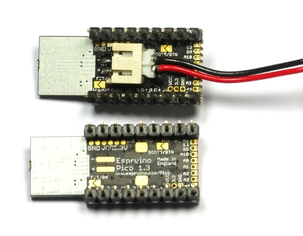
Espruino Pico contains the circuitry needed to power itself from a battery without the voltage drop of a diode. This means that it will run off of normal 3.7v LiPo batteries (or any voltage up to 16v).
In order to connect to a battery, you can use either the pins marked Bat and GND (on opposite sides of the board, nearest the USB connector), or you can solder a JST S2B-PH-SM4-TB Battery connector connector onto the underside of the board.
Please see the Battery page for information on connectors and where to buy them.
Alternate USB connectors
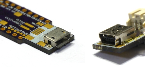
On the rear of the Pico Board under the while block of silkscreen, there are pads for connectors. Espruino rev 1v3 has both Micro and Mini USB, but Espruino rev 1v4 only has Mini USB (due to potential issues with Apple's USB extension leads).
To use these, carefully scratch off the silkscreen until you have copper tracks, and solder on the connector.
The connectors you need are very standard parts. While some parts are listed below, many other parts from many different manufacturers would work perfectly well.
Mini-B USB
(Pico Revision 1v3 and 1v4) - 5 pin, 4 pad surface mount
Micro-B USB
(Pico Revision 1v3 only) - 5 pin, 2 pad surface mount
Power, and the FET/B0 Jumper
| Pico Board | Quick Reference | Circuit Diagram (below) | Description |
|---|---|---|---|
| USB Plug | VUSB | USB voltage in | |
| VCC | 5V | 5V | USB voltage output (minus diode drop) if connected, Battery voltage if not |
Bat (also pad marked +) |
BAT_IN | VBAT | Battery voltage input (connect battery here) |
| 3.3V | VDD | VDD | Regulated 3.3v output (~200mA continuous) |
Currently the labelling for the Pico's pins is quite confusing (it's different on the circuit diagram, PCB silkscreen, and the Pinout diagram). Hopefully the table above will help to clear it up slightly.
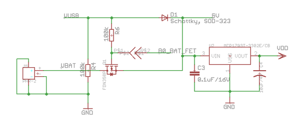
Espruino's power circuitry is as above. When USB is connected the device is powered through a Schottky diode with 0.3v voltage drop. However when USB is disconnected then Espruino can be powered from a battery with no voltage drop. This is done by turning on the PFET Q1.
However, the FET/B0 Jumper allows you to connect the PFET's gate to pin B0. This allows you to do several things:
- Check whether the device is running from USB or Battery (
digitalRead(B0)?"USB":"Bat") - When running from USB, use the
BatPin as a powered 5V output. - When running from USB with a battery connected, charge the battery.
This last reason is why the jumper is disconnected by default. It could be dangerous to charge a LiPo battery this way unless your software also monitor's the battery's charge.
Once the FET/B0 Jumper is shorted, the following commands will work:
digitalWrite(B0,0); // Turn on the 'Bat' output fully
digitalWrite(B0,1); // Partially turn on the 'Bat' output (this produces 3.3v on the FET, meaning it has just 1.4v between Gate and Drain)
digitalRead(B0); // turn off the output (also check if USB powered)
pinMode(B0, "af_opendrain");analogWrite(B0, 0.5, {freq:100}); // output a 100Hz 50% duty cycle square wave
The jumper can be shorted by scribbling over it with a normal HB pencil. See the Pico FET Output tutorial for an example.
Firmware Updates
We'd strongly recommend that you use the Web IDE to update the firmware on this board - please see the Firmware Update page for detailed instructions.
If you do manage to erase all your board's flash memory you can use the on-chip bootloader though - see below.
Advanced Reflashing
In very rare cases (if you are experimenting with writing to Flash Memory), you may be able to damage the bootloader, which will effecitively 'brick' the Pico.
To fix this, you'll have to use the hard-wired USB DFU (Device Firmware Upgrade) bootloader. You can also use this method for flashing non-Espruino firmwares to Espruino.
Just:
- Short out the
BOOT0/BTNsolder jumper on the back of the board - you can do this by drawing over it with a pencil. - Install ST's DFU utility on Windows, or dfu-util for Mac or Linux
- Download the latest Espruino Pico binary from the download page (Cutting Edge builds will not work as these don't include a bootloader)
- Hold down the Pico's button while plugging it into USB
- Use the DFU tool to flash the firmware. Using the GUI on windows, or with the command
sudo dfu-util -a 0 -s 0x08000000 -D espruino_binary_file.binfordfu-utilon Mac/Linux. - Un-short the
BOOT0/BTNjumper to re-use the original Espruino Bootloader. If you used a Pencil mark then you may need to use cleaning fluid and a small brush to totally clear out the graphite.
Note: If you can't access the bottom side of the board (maybe it is soldered down), on rev 1v3 boards BOOT0 is available via a gold teardrop-shaped pad on the top of the board. Short this to 3.3v while applying power to enable DFU mode (holding down the button is then not required).
Advanced Debugging
The Pico also has SWD Debug connections on the back of it. An ST-Link debugger (or ST Discovery/Nucleo board) can be connected to these connections for fast firmware uploads and source-level debugging of the interpreter itself.
See the AdvancedDebug page for more information.
Other Official Espruino Boards


This page is auto-generated from GitHub. If you see any mistakes or have suggestions, please let us know.