MDBT42Q Bluetooth Module
Buy Now
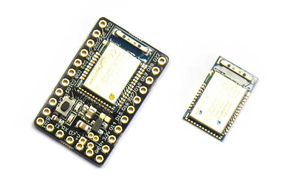
The MDBT42Q is the Bluetooth module that we use in Puck.js and Pixl.js devices. You can get it with Espruino installed in two forms:
- Breakout board with 0.1" pins, voltage regulator, Button and LEDs
- Bare module (0.7mm pin pitch, surface mount)
Just got your MDBT42Q? Take a look here!
Note: We only provide support for MDBT42 modules purchased from us. Other modules don't have a bootloader installed and will need connecting to a programmer tool to have firmware installed.
Contents
Features
- Bluetooth Low Energy
- Espruino JavaScript interpreter pre-installed
- nRF52832 SoC - 64MHz ARM Cortex M4, 64kB RAM, 512kB Flash
- 32 x GPIO (capable of PWM, SPI, I2C, UART) on 0.7mm Pitch, including 8 analog inputs
- 1.7v - 3.6v voltage range (on bare module)
- Built in thermometer
- NFC tag programmable from JavaScript (when an antenna is connected)
- Dimensions: 16mm x 10mm x 2.2mm thick
Breakout board features
- 2.5 - 16v voltage input (on breakout board), 20uA power draw when advertising
- 0.1" pin header (With 22 GPIO, 7 analog inputs)
- Red and Green LEDs
- Button
Getting Started
Check out the section below on Powering - the bare MDBT42Q module and the breakout have slightly different requirements.
Once powered up follow the Getting Started Guide for details on getting the IDE connected wirelessly. You can also use a wired connection if you prefer.
Powering MDBT42Q
Breakout board
Apply power between any V+/Vin and GND pins. Any voltage between 2.5 and 16 volts
will work - just be careful not to get the polarity wrong! Check the pinout below
for more information on the location of pins.
Just between Vin/GND and D9/D10 on the bottom edge of the board in the pinout
there are two 2mm-spaced pins. These can be used to fit a JST PHR-2 battery connector
as mentioned on the Battery page - these are very common for LiPo batteries,
which are a good fit for the module.
Bare Module
All you need to get the MDBT42Q working is to apply power between the VDD and
GND pins. A 3v non-rechargeable lithium cell is ideal for this (LiPo batteries
have a voltage that is too high and will need the voltage dropping with a diode
or voltage regulator). Check the pinout below for details on where to
connect power.
It is recommended to connect all the GND pins together (especially when
designing a PCB) but it is not absolutely required - you can boot the
MDBT42Q module with just two wires.
Power Consumption
- No advertising - 5uA
- Advertising - 80uA
- Connected via BLE - 900uA (idle 40uA)
- LED1 on - 10mA
- 100% CPU usage running JavaScript - 8mA
- Using NRF.findDevices to scan for devices - 12mA
On-board peripherals
While there are no buttons or LEDs on the bare module, the MDBT42Q build assumes the following (which are connected on the breakout board):
- There is a button (
BTN/BTN1) between pinD0and 3.3v. Pulling this high on boot enables the bootloader. - There is a LED (
LED/LED1) between pinD1and GND. This is flashes at boot and also indicates bootloader mode.
The breakout board also contains a green LED (LED2) on pin D2 (Espruino 1v99 and earlier require global.LED2=D2 to use this). Since D2 is an analog input it is possible to detect ambient light using analogRead(LED2) - values range from around 0 (dark) to 0.25 (bright).
Hard Reset
Occasionally you may manage to save code to your MDBT42Q that then runs at boot and stops you connecting to it, effectively 'bricking' it.
Recovering it easy:
- Follow the step for a firmware update, but leave
BTN/D0pressed/connected for 5 seconds (or until the LED goes out). - Espruino will now have booted without loading any saved code, however the code will still be there and the next time you reset it the code will be loaded as normal.
- You can now connect normally with the IDE and continue.
- To reset completely, type
reset(true)into the REPL. This will remove any saved code that is present in the MDBT42Q so even after a reset, your code will not be loaded.
Tutorials
First, it's best to check out the Getting Started Guide
Tutorials using MDBT42Q:
 Battery Monitor
") Advanced Debug (SWD)
Advanced Debug (SWD)
") Quick Start (Bluetooth LE)
Quick Start (Bluetooth LE)
 Tiny Word Clock
 nRF52 Low Level Interface Library
 Night Light
 Time Machine Retro-Inspired Smartwatch
 Rubble Watch
 Bluetooth Energy Usage Monitor
 Electric Skateboard Controller
 Wooden Bluetooth Remote for Lego Duplo Train
") Quick Start (Writing Code)
Quick Start (Writing Code)
 BLE Communications
 nRF52 Accurate Stepper Motor Driver
Tutorials using Bluetooth LE:
 BTHome Library
 Bluetooth Characteristic Notifications
 LEGO WeDo 2.0
") LEGO Power Functions Clone Remote Control (Mould King M-0006 / Kaiyu / Bandra / AKOGD / MayD / etc)
LEGO Power Functions Clone Remote Control (Mould King M-0006 / Kaiyu / Bandra / AKOGD / MayD / etc)
 Pixl.js Bluetooth to Ethernet MQTT Bridge
 Bluetooth LE Printers
 Bluetooth LE Emoji Advertising
 Tilt Hydrometer Repeater
 BLE Advertising with Node.js/Python/C#/Android
 Automatic Data Download
 Puck.js to GCP BigQuery & Data Studio
 Stream from Puck.js to AWS IOT Core & SNS Email
") Bluetooth LE UARTs (NUS)
Bluetooth LE UARTs (NUS)
 Bluetooth LE HID Keyboards
 Bluetooth LE Security and Access Control
 Bluetooth LE MIDI
 Web Bluetooth on Linux
 Bluetooth Time Setter
 Using Web Bluetooth with Espruino
 Bluetooth LE and If This Then That
 UART.js Library
 Eddystone Beacons
 Bluetooth LE and Node-RED with MQTT
 Bluetooth Music Controller
 Controlling Bluetooth Lights with Puck.js
 Bluetooth LE HTTP Proxies
 Exercise Machine controlled Video
") About Bluetooth LE (BLE)
About Bluetooth LE (BLE)
 Puck.js with SMS control
 Pixl.js SMS Remote Monitoring
 Web IDE on a Raspberry Pi
 Puck.js Bluetooth with the Graphical Editor
 Controlling Other BLE Espruino Devices
 Pixl.js Simple Logger
 Pixl.js Multiplayer Pong Game
BLE Characteristic Scan
LED BLE Library
Bluefruit LE app interface
Pixl.js Multiplayer Pong Game
BLE Characteristic Scan
LED BLE Library
Bluefruit LE app interface
Tutorials using Bluetooth LE and functionality that may not be part of the MDBT42Q module:
 DIY Smart Meter
 BTHome and Home Assistant Setup
 BTHome Door Sensor for Home Assistant
 Water Level Monitor
 Puck.js Vibration Sensor
 Interfacing to a PC
 Pixl.js Wireless Temperature Display
 Turning an Espruino Puck.js Into a Universal Presentation Clicker
 Controlling Espruino from Tensorflow on the Desktop
 Bookmarklets with Web Bluetooth
 Bangle.js Data Streaming
 Puckmote - Universal Remote Control
 IoT for Kitchen Gardens
 Talos, Keeping You Safe During Your Commute
 Puck.js Control from Android using DroidScript
 Ikea Eneby Speaker Controller
 Pixl.js Wireless Weather Station
 Temperature Controlled Night Light with Puck.js
 Infrared Record and Playback with Puck.js
 Door Controlled Light with Puck.js
 Freezer Alarm
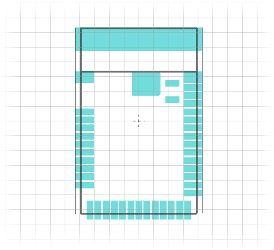
Pinout
Hover the mouse over a pin function for more information. Clicking in a function will tell you how to use it in Espruino.
- Purple boxes show pins that are used for other functionality on the board. You should avoid using these unless you know that the marked device is not used.
- ! boxes contain extra information about the pin. Hover your mouse over them to see it.
- 3.3v boxes mark pins that are not 5v tolerant (they only take inputs from 0 - 3.3v, not 0 - 5v).
- 3.3 is a 3.3v output from the on-board Voltage regulator.
- GND is ground (0v).
- ADC is an Analog to Digital Converter (for reading analog voltages)
- USART is a 2 wire peripheral for Serial Data.
MDBT42Q module
MDBT42Q breakout board
Note: The nRF52 port has one available I2C, SPI and USART (and infinite software SPI and I2C). Unlike STM32-based Espruino boards, these peripherals can be used on any pin.
The bare MDBT42Q module must be powered with a voltage between 1.7v and 3.6v. You can not connect a LiPo battery to it without a voltage regulator. However the breakout board contains a regulator that will work off of 2.5 to 16 volts.
Information
- There's an MDBT42Q API reference here
- Eagle CAD footprint
- Eagle design files for breakout board and simple beacon
- PDF schematic and board layouts for breakout board and simple beacon
- nRF52832 Datasheet
- MDBT42 Datasheet
Certifications:
- The MDBT42Q radio module has certifications for FCC (USA), CE(EU), TELEC (Japan), SRRC (China), IC (Canada), NCC (Taiwan) and KC (South Korea)
Serial Console
When power is first applied, the MDBT42Q checks if pin D8 (labelled RX on the breakout board) is at 3.3v (which will be the
case if it is connected to a Serial port's transmit line). If it is, it initialises
the on-chip UART on D8 (MDBT42Q RX) and D6 (MDBT42Q TX) and puts the Espruino
console (REPL) on it at 9600 baud.
To use it, connect to a 3.3v output USB to TTL converter as follows:
| MDBT42Q | USB->TTL converter |
|---|---|
GND |
GND |
D8 (RX) |
TX ( <- PC ) |
D6 (TX) |
RX ( -> PC ) |
3V |
3.3v (Optional - to run without a battery) |
You can now use the normal Espruino Web IDE, or a serial terminal application at 9600 baud.
When you connect via Bluetooth, the console will automatically move over. To
stop this, execute Serial1.setConsole(true) to force the console to stay on
Serial1.
Note: Serial1 is not enabled by default because it requires the high speed oscillator to stay on, which increases power draw a huge amount. If you connect the UART but don't power down and power on the MDBT42Q, you won't get a serial port.
Firmware Updates
Please see the Firmware Update page for detailed instructions.
Note: If you hold BTN (or leave D0 connected to VDD) for too long (> 3 sec),
the MDBT42 will leave bootloader mode and will instead start Espruino without loading
saved code, allowing a hard reset to be performed.
Other Official Espruino Boards


This page is auto-generated from GitHub. If you see any mistakes or have suggestions, please let us know.