SSD16XX e-Paper display driver
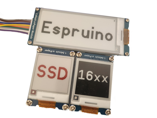
E-ink display with a display driver of SSD16XX (Ex - SSD1681) are a family of similar controller set with different properties. Some with color options or with the ability to do partial refreshes.
Tested with
- SSD1681 (W)(C)
Functionality is provided by the SSD16XX (About Modules) module, using the Graphics library.
Notes
- The display can be read perfectly in harsh sunlight, but has no back lighting.
- E-paper displays are not known for fast refresh cycles.
- E-paper displays need only power for updating the display, not for keeping it up.
Wiring Up
The bare display and controller module needs to be connected with a 24pin FPC connector with 0.5mm pitch and an additional driving circuit. There are rather huge and expensive ready to use development boards available from the display manufacturer. You can even try to build the minimum circuit yourself, e.g. like Jaroslav Sýkora did.
The following infos apply only to the connection between a common display and a microcontroller, ignoring the driving circuit.
Pin overview
| SSD16XX | Notes |
|---|---|
| GND | Ground |
| SDA | SPI mosi pin. The SSD16XX provides no miso pin. |
| SCL | SPI Clock pin |
| CS1 | Chip select pin, is used to prepare the SSD16XX to receive data over SPI. Pull High before you send data over SPI. |
| D/C | Data/Command control pin, is used to prepare the SSD16XX to receive either commands (pulled LOW) or data (pulled HIGH) over SPI. |
| Res | Hardware Reset pin, pull LOW to reset the SSD16XX. |
| BU | This pin is Busy state output pin When Busy is High, the operation of the chip should not be interrupted, command should not be sent. |
| BS1 | Pin for selecting SPI wire mode, pull LOW for 4-wire mode and HIGH for 3-wire mode. |
| 3.3v | Power pin. |
The SSD16XX provides two types of SPI interface modes, but the module supports 4-wire mode only.
SPI-Mode 4-wire
In 4-wire mode you need to set the D/C pin before each SPI send to signal either a command or data will be send. The module takes care of that for you.
Wiring example for SPI 4-wire mode
| SSD16XX | Espruino Pico | Notes |
|---|---|---|
| GND | GND | |
| SDA | B5 | B5 is SPI-1 mosi on Espruino Pico, you can also use SPI-2 or SPI-3. |
| SCL | B3 | B3 is SPI-1 clock on Espruino Pico, you can also use SPI-2 or SPI-3. |
| CS1 | B6 | You can use any of the GPIO pins on the Espruino Pico. |
| D/C | B7 | You can use any of the GPIO pins on the Espruino Pico. |
| Res | A5 | You can use any of the GPIO pins on the Espruino Pico. |
| BU | A8 | You can use any of the GPIO pins on the Espruino Pico. |
| BS1 | A6 | You can use any of the GPIO pins on the Espruino Pico or connect it to either GND or 3.3v. |
| 3.3v | A7 | You can use any of the GPIO pins on the Espruino Pico to have full control or connect it to 3.3v. |
Software
Example
//Example using a Nordict NRF52840DK
var screen = require("SSD16XX");

var sck  = D47;
var mosi = D45;
SPI1.setup({mosi:mosi, sck:sck, baud: 4000000,order:'msb', bits:8});

var cs   = D44;
var busyPin = D43;
var dcPin = D42; //Data/Command
var resetPin = D40;

var screenSettings  = {
  display: {
    bpp : 1,
    displaySizeX      : 200,
    displaySizeY      : 200,
    coloredDisplay    : 1
  },
  spi: SPI1,
  csPin: D44,
  busyPin: D43,
  dcPin: D42,
  resetPin: D40
};

console.log("[Program started]");

screen.fullReset().then(() => {
  console.log("[screen init]");
  return screen.init();
}).then(() => {
  screen.g.clear(0x00);
  screen.g.cw.setFontVector(100);
  screen.g.cw.setColor(1).drawString("1",75,50);
  console.log("drawing a one");
  return screen.g.flip();
}).then(()=>{
  console.log("[got here 2]");
  screen.g.clear(0x00);
  screen.g.cw.setFontVector(100);
  screen.g.cw.setColor(1).drawString("2",75,50);
  console.log("[drawing a two]");
  return screen.g.flip();
}).then(()=>{
  console.log("done");
  screen.sleep();
})
This code will only start after sending it to your device and run the save(); command on the left side of web ide.
Double Buffer
This module uses a double buffer, which means you need to call display.g.flip() before any changes take effect.
Rotation
You can rotate the display with display.g.setRotation(1);.
It might be possible to work around this with fiddling around with the gate scanning mechanism (see specification). Right now this seems to be the easiest solution.
Fast refresh rate.
When you enable display.setFastRefresh() the display will only change the changed pixels. Instead of going through then entire refresh cycle. This will increase the displays refresh rate, but might cause burn into the display. So its recommended to do a setFullRefresh to fully reset the display pixels. But if you do this. You'll have to use this SetFastRefresh to make the display only refresh partially.
Colors
Default background color
The Graphics library is used with a buffer in this module.
Per default all pixels in this buffer have their color set to 0. For the SSD1606 this means black. To adjust the buffer default values, a clear(color) function is provided, use as:
Color black and white displays
| Color B/W | Values for using with clear() |
Values for using with setColor() |
|---|---|---|
| white | decimal 255, or hexadecimal 0xFF |
decimal 1 or hexadecimal 0x01 |
| black | decimal 0, or hexadecimal 0x00 |
decimal 0 or hexadecimal 0x00 |
Color black and white and color (Red or Yellow) displays
| Color Red/Yellow | Values for using with clear() |
Values for using with setColor() |
|---|---|---|
| red decimal | 255, or hexadecimal 0xFF |
decimal 1 or hexadecimal 0x01 |
| white/black | decimal 0, or hexadecimal 0x00 |
decimal 0 or hexadecimal 0x00 |
Pixel Colors under the hood
The way color is handle is with black and white is with a single buffer, but to have color it requires 2 buffers. One for black and white and one that either enables or disables the given (red/yellow) color in that given pixel. Its structured this way because thats how hardware registers hold the data.
The reverse order of pixels to concrete bits is taken care of by the module with a suitable Graphics configuration.
Graphics.createArrayBuffer(
            displaySizeX,
            displaySizeY,
            bpp,
            {msb: true} // this does the magic for the reverse part
);
The clear() function works with setting a complete byte for 4 pixels at once. All other function set individual pixels.
Pin Configurations
For the module to work you need to provide:
resetPindcPinbusyPincsPin- a configured SPI without miso pin.
Notes on the optional power pin
If you do not provide a power pin, the on(); and off(); functions do not work.
Notes for the optional bs1 pin
The module can set the SPI wire mode independently for you, just provide the BS1 pin.
Example with provided BS1 pin:
  var display = require('SSD16XX').connect({
    // other configurations
    dcPin      : a Espruino GPIO pin,
    bs1Pin     : a Espruino GPIO pin
  });
Example without provided BS1 pin, D/C pin is still needed:
  var display = require('SSD16XX').connect({
    // other configurations
    dcPin      : a Espruino GPIO pin
  });
Display Configuration
This module needs a concrete display configuration.
If you want to use another display, you can provide its configuration with:
  var display = require('SSD16XX').connect({
    display: {
      bpp               : 1 or 2 or 4,
      displaySizeX      : int,
      displaySizeY      : int,
      lutRegisterData   : new Uint8Array(),
      coloredDisplay    : boolean
    },
    ... other configurations
  });
Developing notes - helpful resources
Reference
/* Power on the display, using the provided powerPin.
 */
SSD16xx.prototype.on = function () { ... }

/* Power off the display, using the provided powerPin.
 */
SSD16xx.prototype.off = function () { ... }

/* Enters deep sleep and needs a hwReset to enable it again
 */
SSD16xx.prototype.sleep = function () { ... }

/* Use resetPin to make a hardware reset.
 * @param {Function} callback - callback function
 */
SSD16xx.prototype.hwReset = function () { ... }

/* Send command to the controller.
 * @param command - the command int
 */
SSD16xx.prototype.sc = function (command) { ... }

/* Send data to the controller.
 * @param data - the data
 */
SSD16xx.prototype.sd = function (data) { ... }

/* Send command and data to the controller.
 * @param command - the command
 * @param data - the data
 */
SSD16xx.prototype.scd = function (command, data) { ... }

/* Does hardware reset and then does a software reset.
 * @param {Function} callback - callback function
 */
SSD16xx.prototype.fullReset = function () { ... }

/* Send a cmd and optional data.  Then waits for the device to be ready
 * @param {Function} callback - callback function
 */
SSD16xx.prototype.waitCmd = function (command, data) { ... }

/* Sends the refresh dispaly command and then waits
 */
SSD16xx.prototype.refreshDisplay = function (command) { ... }

/* Initialize display.
 * If set it uses the provided bs1Pin to configure the SPI mode between to use 4 lines.
 * Initializing sequence:
 * <ol>
 * <li>Exit deep sleep mode</li>
 * <li>Set region of the display to full and increment in positive both in Y and X</li>
 * <li>[optional] LUT init</li>
 * </ol>
 * @param {Object} options - provided options, useBs1Pin and clearScreenColor
 * @param {Function} callback - callback function
 */
SSD16xx.prototype.init = function () { ... }

/* Sets a partial region of the display.
 * @param {Function} x,y w=width and h=height
 */
SSD16xx.prototype.setPartialRegion = function (x, y, w, h) { ... }

/* Sets display to do full refreshes
 */
SSD16xx.prototype.setFullRefresh = function () { ... }

/* SetFastRefresh - is used make the device refresh the display in only the changed pixels.
 * This will increase the displays refresh rate, but might cause burn into the display.
 * So its recommended to do a (setFullRefresh) to fully reset the display pixels.  But if you do this.
 * You'll have to use this SetFastRefresh to make the display only refresh partiaily.
 */
SSD16xx.prototype.setFastRefresh = function () { ... }

/* flip - Sets up to wrights the full buffer to the display and then waits for a refresh.
 */
SSD16xx.prototype.flip = function () { ... }

/* Clear the buffer based on a specific color.
 * @param {clearColor} - The color will be in byte size.  So properly duplicate bit colors to a byte.
 */
SSD16xx.prototype.clear = function (clearColor) { ... }

/* Rotates the buffer
 * @param {rotation} - Rotation in 0-3 with each being a 90 degree rotation.
 */
SSD16xx.prototype.setRotation = function (rotation) { ... }

/* Black and white display buffer.
 * Creates the Graphics object with Graphics.createArrayBuffer(...).
 * Sets the display x size, y size, bits per pixel and msb:true.
 * Provides a clear function to fill in-memory buffer with one color for each pixel.
 */
SSD16xx.prototype.grfxBlackWhite = function () { ... }

/* Red or yellow display buffer for screen that support it.  a
 * Creates the Graphics object with Graphics.createArrayBuffer(...).
 * Sets the display x size, y size, bits per pixel and msb:true.
 * Provides a clear function to fill in-memory buffer with one color for each pixel.
 */
SSD16xx.prototype.grfxColorWhite = function () { ... }

// Export the module.
exports.connect = function (options) { ... }
This page is auto-generated from GitHub. If you see any mistakes or have suggestions, please let us know.