Remote Control Sockets
Introduction
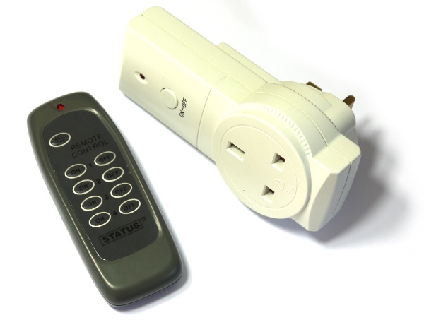
You can now buy remote controlled sockets very cheaply. If you want to turn some mains-powered things on and off with your computer but don't want to get involved with Relays and wiring up mains then controlling these could be a great idea.
We're going to use 'Status'-branded sockets.
With these sorts of remote-controlled devices there are two ways of controlling them.
The Easy Way
Open up the remote control and then connect wires from Espruino to each pushbutton. This way, you can simply control whatever you want by faking a button press.
The Hard Way
Or, you can buy a radio transmitter and can then try and duplicate the remote control's functionality. This is harder, but more flexible (you could control lots of sockets), and obviously more fun!
The sockets I'm using are 433.92Mhz ones (it's written on the back). This band is an 'open' band - you don't need a license to use it, and it's a complete free for all. Every device has its own protocol, and they all transmit whenever they want. This means that there is quite a large likelihood that the signal that you send will not arrive intact so most devices send the same signal several times.
The Protocol
Unless you have a storage oscilloscope, working out the protocol of your particular sockets is remarkably difficult. In order to make the tutorial a bit easier I've described it below. There's also this post on the PicAxe forum that describes it very well.
- There are 25, equally spaced bits
- A '1' is represented as 0.9ms ON, and then 0.3ms OFF
- A '0' is represented as 0.3ms ON, and then 0.9ms OFF
- The 25 bits are repeated continuously (as long as the button is pressed), with a pause between them of around 8ms.
You'll Need
- An Espruino Board
- A 433Mhz Radio transmitter/receiver pair
- A CC3000 module (if you want to web-enable your sockets)
Working out your code
By far the easiest way to work our your code (and if your remote control sockets use the same protocol) would be to use a digital storage oscilloscope, but we'll try and use the Espruino here.
Wire the 433Mhz receiver up as follows:
| 433Mhz | Espruino |
|---|---|
| GND | GND |
| VCC | 3.3 |
| DATA | A0 |
Note: We're using below the suggested voltage here, because it makes the receiver less sensitive and less likely to receive signals from transmitters that are further away.
We know what the protocol is (above) so we'll try and make something to understand it...
Add the following code:
function startListening(pin) {
  // The data we have received so far
  var n="";
  // The handler that gets called when the signal changes state
  function sig(e) {
    var d = 10000*(e.time-e.lastTime);
    if (d<2 || d>10) {
      if (n.length>20) console.log(n);
      n="";
    } else if (!e.state) n+=0|d>5;
  }
  // start listening for a change
  setWatch(sig, pin, {repeat:true, edge:"both"});
}

startListening(A0);
The function sig is quite hard to understand. It has been written such that the code executes relatively quickly, so it is explained in more detail (with comments) below:
  function sig(e) {
    // set d to the time (in 0.1ms) the pulse was high or low for (makes the numbers nice and easy later on!)
    var d = 10000*(e.time-e.lastTime);
    // If the pulse length is really out of range...
    // we were looking for 0.3ms or 0.9ms, so throw out anything
    // less than 0.2 or greater than 1ms
    if (d<2 || d>10) {
      // it's out of range...
      // if we had enough data, it could be our signal - print it!
      if (n.length>20) console.log(n);
      // now empty it
      n="";
    } else if (!e.state) {
      // Signal length was in range, and check that the current pin
      // state is 0 - this means a pulse has just ended, so what we
      // have is the length of the pulse in `d`

      // Now, we're just adding a '1' or a '0' to the string `n`

      // This is basically:
      // if (d>5) n+="1" else n+="0";

      // But `d>5` is a boolean to we make it an int by `or`ing it with `0`
      // Luckily the precedence of `|` is such that `d>5` happens before `0|`
      n+=0|d>5;
    }
  }
Put the transmitter right next to the receiver and press one of the buttons. You should see a bunch of lines that are all the same (and a few corrupted ones!). They'll look something like:
0000010100000111111101110
0000010100000111111101110
0000010100000111111101110
0000010100000111111101110
0000010100000111111101110
0000010100000111111101110
0000010100000111111101110
0000010100000111111101110
This is the transmitted code...
Try pressing different buttons, and you should notice that the numbers at the beginning are the same, and the ones at the end change (except the final 0). It should all look something like:
| Button | Code |
|---|---|
| ALL OFF | ...10000 |
| ON 1 | ...11110 |
| OFF 1 | ...01110 |
| ON 2 | ...10110 |
| OFF 2 | ...00110 |
| ON 3 | ...11010 |
| OFF 3 | ...01010 |
| ON 4 | ...11110 |
| OFF 4 | ...01110 |
So now we've worked out the code, we can write a transmitter...
Making the Transmitter
Wire the 433Mhz transmitter up as follows:
| 433Mhz | Espruino |
|---|---|
| GND | GND |
| VCC | BAT |
| DATA | A0 |
And now reset Espruino and put in the following code, replacing the number in CODE with any of the block of numbers that you got.
var TX = A0;
var CODE = 0b0000010100000111111101110;

function sendCommand(command) {
  var bits = (CODE & ~0b11111) | command;
  for (var i=24;i>=0;i--) {
    if ((bits>>i)&1) {
      digitalPulse(TX,1,0.9);
      digitalPulse(TX,0,0.3);
    } else {
      digitalPulse(TX,1,0.3);
      digitalPulse(TX,0,0.9);
    }
  }
  digitalPulse(TX,1,0.001);
}

function sendMultiple(command) {
  var n = 10;
  var interval = setInterval(function() {
    sendCommand(command);
    if (n-- < 0) clearInterval(interval);
  }, 50);
}

var socketOn = false;
setWatch(function() {
  socketOn = !socketOn;
  sendMultiple(socketOn ? 0b11110 : 0b01110);
}, BTN1, { repeat:true, edge:"rising", debounce:10 });
Now you'll find that when you press BTN1, it will turn Socket 1 either on or off!
Internet Enablement
Next, Wire up the CC3000 as described in this link and use the following code (Changing the WiFi access point and code):
var TX = A0;
var CODE = 0b0000010100000111111101110;

function sendCommand(command) {
  var bits = (CODE & ~0b11111) | command;
  for (var i=24;i>=0;i--) {
    if ((bits>>i)&1) {
      digitalPulse(TX,1,0.9);
      digitalPulse(TX,0,0.3);
    } else {
      digitalPulse(TX,1,0.3);
      digitalPulse(TX,0,0.9);
    }
  }
  digitalPulse(TX,1,0.001);
}

function sendMultiple(command) {
  print("send "+command);
  var n = 10;
  var interval = setInterval(function() {
    sendCommand(command);
    if (n-- < 0) clearInterval(interval);
  }, 50);
}

function pageHandler(req, res) {
  res.writeHead(200, {'Content-Type': 'text/html'});
  var u = url.parse(req.url, true);
  res.write('<html><body>Socket <a href="/?s1=on">on</a> or <a href="/?s1=off">off</a></body></html>');
  if (u.query !== null) {
    if (u.query["s1"]=="on") sendMultiple(0b11110);
    if (u.query["s1"]=="off") sendMultiple(0b01110);
  }
  res.end();
}

var wlan = require("CC3000").connect();
wlan.connect( "AccessPointName", "WPA2key", function (s) {
  if (s=="dhcp") {
    console.log("Connect to http://"+wlan.getIP().ip);
    require("http").createServer(pageHandler).listen(80);
  }
});
When it instructs you to connect to an IP address, type it into your web browser. You should now see a simple Webpage with Socket on or off written on it. Click on either to change the state of Socket 1!
This page is auto-generated from GitHub. If you see any mistakes or have suggestions, please let us know.