Bangle.js 2 Technical Information
For general Bangle.js information, try the Bangle.js 1 or the Bangle.js 2 pages
This page contains detailed information on Bangle.js's 2's internals. If you're just writing JS then you should have no need for this information, but if you plan on modifying the Bangle.js firmware it might be of interest.
This file is based on reverse engineering of publically available firmware and information, buy Gordon Williams, fanoush, and atc1441. It was originally published as a hackaday.io project page
Contents
Features
- IP67 Water Resistant (everyday use, not swimming or baths)
- Nordic 64MHz nRF52840 ARM Cortex-M4 processor with Bluetooth LE
- 256kB RAM 1024kB on-chip flash, 8MB external flash (GD25Q64C/GD25Q64E)
- 1.3 inch 176x176 always-on 3 bit colour LCD display (LPM013M126)
- Full touchscreen (Hynitron CST816D)
- Single button on side of watch
- GPS/Glonass receiver (AT6558 / AT6558R)
- Heart rate monitor (Vcare VC31 / VC31B)
- 3 Axis Accelerometer (Kionix KX022)
- 3 Axis Magnetometer
- Air Pressure/Temperature sensor (Bosch BMP280 / Goertek SPL06)
- Vibration motor
- SWD program/debug pins on rear of watch
- 175mAh battery (XK302627, 3 x 26 x 27mm), 4 weeks standby time
- 36mm x 43mm x 12mm watch body, with standard 20mm watch straps
Software
Where mentioned in the source code or filenames, Q3 references Bangle.js 2, and F18 references Bangle.js 1.
The Espruino version for Bangle.js has a few specific modifications:
jswrap_bangle.ccontains allBangle.*functions and pretty much all Bangle.js functionality.- Some functionality (like menus) is in JavaScript which is built into the firmware. Those JavaScript files are here
BANGLEJS2.pydescribes the build- The
SPIFLASHdevice causesSPIFLASH_BASEto be defined, which enables external SPI flash memory support injshardware.c
- The
If you don't want to use Espruino and would prefer to develop your app as bare-metal in C, check out the example in the BangleJS2BareMetal repository
Hardware
The watch body is made of ABS plastic, with the LCD+touchscreen assembly glued to the front.
Want to get inside? Check out the Bangle.js 2 Disassembly page
There are CAD files for the Bangle.js 2 stand, as well as an STL of the watch body available here
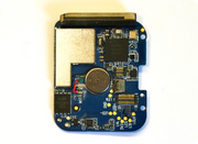
PCB
Below are shots of the Bangle.js 2 PCB:


The components on the PCB are marked here:

SWD
SWD - the 4 pads on the rear of the watch are GND, SWDIO/SWDCLK, VCC. The charge cable has wires for all 4 leads brought out to the USB connector, so the easiest method is just to attach wires from a USB socket to an nRF52DK
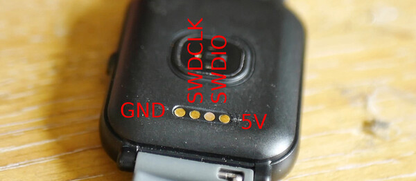
This can be connected to an SWD programmer. We'd recommend using an nRF52 DK (or nRF52840DK).
When using the nRF52DK you'll need to short the GND DETECT pin to GND and short the VTG pin to VDD to tell it you're programming the Bangle.js and not the on-board nRF52. See the example schematic below.

The easiest way to connect to these is to use the provided USB charge cable and to wire up a USB type A socket:
| Pin # | Connect |
|---|---|
| 1 | 5v (not required) |
| 2 | SWDIO |
| 3 | SWDCLK |
| 4 | GND |
Be sure to fully remove the tape and adhesive covering the SWDIO and SWDCLK pins.
See Advanced Debug for more information on programming via SWD.
GPS
The GPS is a AT6558 (or AT6558R on newest Bangle.js devices)
For more information on common usage, check out the Bangle.js 2 GPS page
Espruino handles reception and parsing of NMEA data from the GPS UART when Bangle.setGPSPower(1) is called.
On startup the GPS reports information about itself - this can be viewed with the following (assuming GPS was off before):
Bangle.setGPSPower(1);
Bangle.on('GPS-raw',print);
setTimeout(function() {
  Bangle.removeAllListeners('GPS-raw');
}, 1000);
The first few batches of Bangle.js devices report the following data upon startup, using AT6558 with V5.1.0.0 firmware:
$GPTXT,01,01,02,MA=CASIC*27 false                   # MA = Manufacturer
$GPTXT,01,01,02,IC=AT6558-5N-32-1C510800*48 false   # IC = Chip
$GPTXT,01,01,02,SW=URANUS5,V5.1.0.0*1F false        # SW = Firmware version
$GPTXT,01,01,02,TB=2018-04-18,10:28:16*40 false     # TB = Firmware compile date
$GPTXT,01,01,02,MO=GB*77 false                      # MO = working mode
Newer ones use a AT6558R with V5.3.0.0 firmware.
$GPTXT,01,01,02,MA=CASIC*27 false
$GPTXT,01,01,02,IC=AT6558R-5N-32-1C580901*13 false
$GPTXT,01,01,02,SW=URANUS5,V5.3.0.0*1D false
$GPTXT,01,01,02,TB=2020-03-26,13:25:12*4B false
$GPTXT,01,01,02,MO=GR*67 false
The receiver can be configured with $PCAS commands. It's hard to find decent documentation
on these - the best we have found is a Chinese Language datasheet here.
You need to calculate a checksum when sending, which can be done with the following:
function CASIC_CMD(cmd) {
  var cs = 0;
  for (var i=1;i<cmd.length;i++)
    cs = cs ^ cmd.charCodeAt(i);
  Serial1.println(cmd+"*"+cs.toString(16).toUpperCase().padStart(2, '0'));
}
Here are some example commands that work;
CASIC_CMD("$PCAS03,1,0,0,1,0,0,0,0"); // send only 'GGA+GSV' NMEA data (minimum for Bangle.js GPS event)
// $PCAS03,GGA,GLL,GSA,GSV,RMC,VTG,ZDA,ANT,DHV,LPS...
CASIC_CMD("$PCAS03,1,0,0,1,1,0,0,0"); // send the NMEA packets Bangle.js expects
CASIC_CMD("$PCAS04,1"); // Set to GPS-only mode
/*
1=GPS
2=BDS
3=GPS+BDS
4=GLONASS
5=GPS+GLONASS
6=BDS+GLONASS
7=GPS+BDS+GLONASS
*/
CASIC_CMD("$PCAS02,500"); // Change output speed from default 1000ms to 500ms
// The valid range is 100->1000ms, but to get below 500ms you must disable un-needed packets with PCAS03

CASIC_CMD("$PCAS00"); // Save all changes to flash memory (be careful!)
The receiver also accepts and returns a binary protocol that begins with the characters "\xBA\xCA", but you'll need to consult the CASIC datasheet for more information on that.
We have an English translated version here
There's mention in some forum posts:
- https://forum.espruino.com/conversations/371336/?offset=25#16332430
- https://forum.espruino.com/conversations/371360/
But working code to send/decode packets is:
// Decode CASIC binary packets
Bangle.on("GPS-raw", d=>{
  if (d.substr(0,2)!="\xBA\xCE") return;
  var ab = E.toArrayBuffer(d);
  var dv = new DataView(ab);
  var len = dv.getUint16(2,true);
  var pkt = {
    classId : dv.getUint8(4),
    messageId : dv.getUint8(5),
    payload : new Uint8Array(ab, 4, len),
    crc : dv.getUint32(6+len,true)
  };
  if (pkt.classId == 5 && pkt.messageId==0) pkt.type = "ACK-NACK";
  if (pkt.classId == 5 && pkt.messageId==1) pkt.type = "ACK-ACK";
  print("CASIC", pkt);
});
// Send a binary CASIC packet, eg: {classId:6, messageId:0, payload:[]}
function CASIC_PKT(pkt) {
  pkt.payload = pkt.payload || [];
  var plen = pkt.payload.length;
  var msg = new Uint8Array(10+pkt.payload.length);
  msg.set([0xBA,0xCE,
           plen, // LENGTH
           0x00,
           pkt.classId, // CLASS    ID
           pkt.messageId]); // MESSAGE    ID
  msg.set(pkt.payload, 6);
  var dv = new DataView(msg.buffer);
  // checksum
  var ckSum = 0;
  for (i = -4; i < plen; i+=4)
    ckSum = 0|(ckSum+dv.getUint32(6+i, true));
  dv.setUint32(6+plen, ckSum, true);
  return msg;
}

// Send AID_INI message, {lat,lon,alt}
function AID_INI(pos) {
  var msg = new Uint8Array(56);
  var dv = new DataView(msg.buffer);
  /*
    double                            xOrLat, yOrLon, zOrAlt;
    double                            tow; // 24
    float                            df; // 32
    float                            posAcc; // 36
    float                            tAcc; // 40
    float                            fAcc; // 44
    unsigned int                    res; // 48
    unsigned short int                wn; // 52
    unsigned char                    timeSource; // 54
    unsigned char                    flags; // 55
*/
  var ms = Date.now();
  var wk = (ms-new Date("1980-01-06T00:00:00Z")) / 604800000;
  var wn = Math.floor(wk); // week number
  var tow = (wk-wn) * 604800; // seconds in week
  dv.setFloat64(0, pos.lat, true); // xOrLat
  dv.setFloat64(8, pos.lon, true); // yOrLon
  dv.setFloat64(16, pos.alt, true); // zOrAlt
  dv.setFloat64(24, tow, true); // tow
  dv.setFloat32(32, 0, true); // df
  dv.setFloat32(36, 0, true); // posAcc
  dv.setFloat32(40, 0, true); // tAcc
  dv.setFloat32(44, 0, true); // fAcc
  dv.setUint32(48, 0, true); // res
  dv.setUint16(52, wn, true); // wn
  dv.setUint8(54,0); // timeSource
  dv.setUint8(55, 0x23); // flags ( lat/lon and clock valid, no drift data )
  return CASIC_PKT({classId:0x0B, messageId:0x01, payload:msg});
}
// Query/config UART - just query atm
function CFG_PTR() {
  return CASIC_PKT({classId:6, messageId:0, payload:[]});
}

// Do these a few seconds after GPS has been started

// Request UART config info (quick test)
//Serial1.write(CFG_PTR());
// Set Auxiliary position, time
//Serial1.write(AID_INI({lat : 51.65, lon : -1.267, alt : 30 }));
GPIO
Unlike Bangle.js 1, all IO is connected direct to the nRF52840 - there's no need for an IO expander
| Pin | Connected | State |
|---|---|---|
| 0 | 32876 oscillator | |
| 1 | 32876 oscillator | |
| 2 | PRESSURE_SCL | |
| 3 | Battery voltage analog GND-[1M]-D3-[3M]-VBATT | |
| 5 | MEMLCD_CS (active high) | out |
| 6 | MEMLCD_EXTCOMIN | Needs to be toggled at 5ms or 250ms in sleep all the time |
| 7 | MEMLCD_DISP 1=disp on, 0=disp off | out, pulsed high |
| 8 | Backlight | out |
| 13 (0x0d) | Flash_MISO | input |
| 14 (0x0e) | Flash_CS | out |
| 15 (0x0f) | Flash_MOSI | out |
| 16 (0x10) | Flash_SCK | in_pullup |
| 17 (0x11) | Button | In_pullup, edge detect |
| 19 (0x13) | Vibrate, active=1 | out |
| 21 (0x15) | HRM_POWER, active=1 | out |
| 22 (0x16) | HRM_INT | |
| 23 (0x17) | Charge port | in_pullup |
| 24 (0x18) | HRM_SDA | |
| 25 (0x19) | Charging complete | |
| 26 (0x1a) | MEMLCD_SCK | |
| 27 (0x1b) | MEMLCD_MOSI | |
| 29 (0x1d) | GPS power, active=1 | out |
| 30 (0x1e) | GPS TXD | |
| 31 (0x1f) | GPS RXD | |
| 32 (0x20) | HRM_SCL | |
| 33 (0x21) | TOUCH_SDA | |
| 34 (0x22) | TOUCH_SCL | |
| 35 (0x23) | TOUCH_RESET (active low) | out |
| 36 (0x24) | TOUCH_INT (active low) | |
| 37 (0x25) | ACCEL_SDA | |
| 38 (0x26) | ACCEL_SCL | |
| 39 (0x27) | ACCEL_INT | input |
| 42 (0x2a) | UARX | unused debug pin |
| 43 (0x2b) | UATX | unused debug pin |
| 44 (0x2c) | COMPASS_SDA | |
| 45 (0x2d) | COMPASS_SCL | |
| 47 (0x2f) | PRESSURE_SDA |
To access these pins from Espruino, all you need to do is add D to the pin number. For example to read the analog battery voltage (pin 3), use the command analogRead(D3).
I2C
Bangle.js 2 has the following I2C devices. These are connected via their own pins and don't share an I2C bus - see above for the connections.
- PRESSURE - BMP280, I2C 0x3C(0x1E)
- TOUCH - Hynitron CST816D, I2C 0x2A(0x15)
- HRM - VCare VC31, I2C 0x66(0x33)
- ACCEL - Kionix KX022, I2C 0x3C(0x1E)
- COMPASS - I2C 0x18(0x0C)
Unused pins (adding hardware)
Most of the pins on the nRF52 chip in Bangle.js 2 are either used or not connected. However there are two exceptions - UARX (D42 in Espruino) and UATX (D43 in Espruino). These pins
are not connected to any hardware, but are available as test points so can be connected to whatever you want. They are accessible on the rear of the Bangle.js PCB, under the battery:

There are also test pads for the touchscreen I2C TOUCH_SDA and TOUCH_SCL lines (see GPIO table above) that could be used to connect other I2C devices.
Note: The battery is attached to the back of the Bangle.js PCB with double-sided sticky tape. Take care when removing it, as it's almost impossible to remove the battery without bending it slightly.
If you wish to add your own hardware to Bangle.js, we'd suggest sourcing and fitting a smaller battery, which would then leave room in the rear of the case for your circuitry.
This page is auto-generated from GitHub. If you see any mistakes or have suggestions, please let us know.