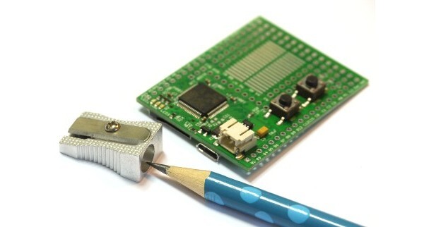
Original Espruino Board
Buy Now
The Espruino Board is a tiny USB-enabled microcontroller with SD card that can be programmed in JavaScript
Just plug it into your computer and get started in seconds with the Web IDE - no software installation needed!
Just got your Espruino Board? Get started here!
Contents
Features
- Less than half the size of a business card ( 54mm x 41mm )
- STM32F103RCT6 32-bit 72MHz ARM Cortex M3 CPU
- 256KB of Flash memory, 48KB of RAM
- Micro USB connector
- Input Voltage Range of 3.6v to 15v
- Battery connector (JST PHR-2 2 Pin)
- Built-in SD card connector
- Red, Green and Blue LEDs
- Pads to allow HC-05 Bluetooth modules to be added
- 0.1" Pin spacing
- 44 GPIO Pins, capable of: 26 PWM Pins, 16 ADC Pins, 3 USARTs, 2 SPI, 2 I2C and 2 DACs
- Prototype area which can be used in many different configurations, for example: Servo Headers, Up to 14x 500mA outputs, 2x .NET Gadgeteer connectors, or NRF24L01+ wireless transceiver modules
- Rev 1v4: CE and RoHS certification
Pinout
Hover the mouse over a pin function for more information. Clicking in a function will tell you how to use it in Espruino.
- Purple boxes show pins that are used for other functionality on the board. You should avoid using these unless you know that the marked device is not used.
- ! boxes contain extra information about the pin. Hover your mouse over them to see it.
- 3.3v boxes mark pins that are not 5v tolerant (they only take inputs from 0 - 3.3v, not 0 - 5v).
- 3.3 is a 3.3v output from the on-board Voltage regulator.
- GND is ground (0v).
- VBAT is the battery voltage output (see the Espruino Board Reference).
- ADC is an Analog to Digital Converter (for reading analog voltages)
- DAC is a Digital to Analog Converter (for creating analog voltages). This is not available on all boards.
- PWM is for Pulse Width Modulation. This creates analog voltages from a digital output by sending a series of pulses.
- SPI is the 3 wire Serial Peripheral Interface.
- USART is a 2 wire peripheral for Serial Data.
- I2C is the 2 wire Inter-Integrated Circuit bus.
- CAN is for the Controller Area Network. It is not supported by Espruino.
Pins not on connectors
Layout
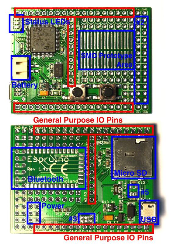
Revision 1.4
Revision 1.3
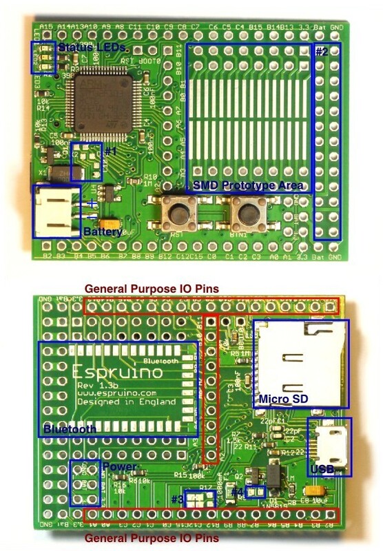
| Name | Function |
|---|---|
| General Purpose IO Pins | See the pinout above for more information about the functionality of these |
| Status LEDs | Red, Green and Blue lights, controllable from Espruino. Access these using the pin names LED1 (red), LED2 (green) and LED3 (blue) |
| Buttons | Below SMD prototype area. Reset button (left) and general purpose button (right). Access this using the pin name BTN |
| SMD Prototype Area | Area that allows you to solder SMD Integrated Circuits such as (ULN2003) and (L293D) |
| Battery | Battery connector, allows any voltage from 3.6v to 15v |
| Bluetooth | Pads for mounting a Bluetooth module |
| Power | Gnd, 3.3v and Battery power pins (see below) |
| Micro SD | A connector for FAT32 formatted Micro SD cards |
| USB | A Micro SD USB connector, for programming and powering Espruino |
| #1 | (r1.3 only) Unpopulated pads for 32kHz crystal. Without this, Espruino will use its internal RC oscillator for timekeeping, which is only accurate to 1-2%. (r1.4 has a 32k crystal preinstalled) |
| #2 | Pin Headers. Each horizontal pair pins in this 2 x 13 area of pins is connected together, so you can solder on a single line of pin header and can then wire from the Prototype area to the other side |
| #3 | cut the shorted link on the right-hand side, solder over the left-hand side, solder a 10k resistor to R17 and you can then use the RST button as a second general purpose button on pin C12 |
| #4 | (r1.3 only) An unpopulated resistor that can trickle-charge a battery when fitted (if the battery is less than 4.3v). See the Battery page for more information - only fit this if you're absolutely sure that your battery type can handle it. |
| #5 | (r1.4 only) An unpopulated area for a MAX1551 LiPo charger IC |
Information
- There's an API reference here
- Circuit Diagram
- Board Layout
- Part library for Eagle CAD
- Part library for Fritzing
- STM32F103RCT6 Datasheet
- STM32F103RCT6 Reference Manual
Tutorials
Links to tutorials that you can do using just the Espruino board:
 Understanding PWM and Implementing it Yourself
") Quick Start (USB)
Quick Start (USB)
 Flashing Lights
") Quick Start (Writing Code)
Quick Start (Writing Code)
 Single Button Combination Lock
 .NET Gadgeteer Modules
 Infrared Remote Control
 Dial Tones
 Using BTN1 to turn on an LED
Tutorials using the Espruino Board:
") Advanced Debug (SWD)
Advanced Debug (SWD)
 Espruino Web IDE
 Tap Tap Rainbow - a 2 Player Quick Reaction Game
 Pocket 'walking' GPS
 KeyPad Timer
 Heater Controller
 Wireless Temperature Sensor
 WiFi Enabled Thermometer
 Water Physics with Servo Motors
 Remote Control Sockets
 Soldering an LCD directly to Espruino
 Motion Sensing Lights
 Morse Code Texting
 MeArm Robotic Arm
 KeyPad Combination Lock
Infrared Remote Control
KeyPad Combination Lock
Infrared Remote Control
 Individually Addressable LEDs
 Graphical Web Interface
Dial Tones
Graphical Web Interface
Dial Tones
 Wifi Remote Console
 WiFi Xively Humidity/Temperature Sensor with Display
 Making Sounds and Music
 Digital Dice
 Simple Data Logger
 Small Solar Powered Espruino
 Mounting the Espruino Board
Temperature Graph on a PCD8544 display, with DS18B20 temperature sensor
Temperature on a PCD8544 display, with DS18B20 temperature sensor
LED Clock (using WS8111)
Remote Control Helicopter with Wii Nunchuck
LED Volume (VU) Meter
Mounting the Espruino Board
Temperature Graph on a PCD8544 display, with DS18B20 temperature sensor
Temperature on a PCD8544 display, with DS18B20 temperature sensor
LED Clock (using WS8111)
Remote Control Helicopter with Wii Nunchuck
LED Volume (VU) Meter
Power
Espruino has 3 ways of powering it - a JST PHR-2 Battery connector, Micro USB, or pin headers.
Both the Micro USB and Battery connector can power the device (and pin headers), and the source of power will be automatically switched. If you power Espruino via the Pin Headers, do not plug a battery in, and do not plug in USB unless you are powering it with 5v or more.
If you wish to power Espruino from mains, we'd suggest using a Micro USB phone charger. This are widely available as the majority of mobile phones (with the exception of iPhones and low-end Nokias) now use them.
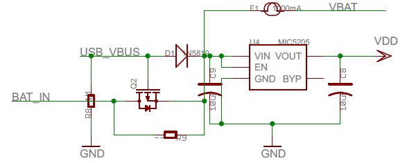
In order to protect the Espruino board (and what it is connected to), a 1000mA thermal (self-resetting) fuse is on the board between the pins marked 'Bat' on the board and the power source (USB/Battery).
See Connecting Batteries below for information on connecting Batteries.
Note: On rev 1v3 the voltage regulator draws 80uA, which makes up the majority of the 110uA power draw when sleeping. rev 1v4 has a much more efficient regulator, which allows a power draw of just 30uA.
Connecting
NOTE: The Espruino board has no case and so the USB connector is completely unsupported. This means it is relatively delicate (especially on rev 1v3 boards) and needs to be treated carefully. Try and pull the connector straight out, and do not push down on the board when the connector is inserted, or try and move the board around using the cable.
Pin Strip
There's a Pin Strip page covering how to solder Pin Strip onto the Espruino Board
Batteries
You can usually buy batteries with the PH-type 2 pin female JST (PHR-2) connector ready-soldered, see Battery for more details on battries and connectors.
Servo Motors
See the Pin Strip page for ideas on how to connect servos, and the Servo Motors page on how to control them.
Motor Drivers
To drive motors there are two good options - both of which solder on to the prototype area (which is designed for SOIC-style chips). The surface mount versions of these will require some soldering skills, so if you only need to turn motors on and off (and not drive them at different speeds) then a Relay Module might be easier.
L293D
The L293D is slightly more expensive, but has four outputs, each of which can pull up to a voltage as well as down to 0v. This makes it ideal for driving motors in forwards and reverse, as each side of the motor can be connected to an output.
ULN2003
The ULN2003 has 7 x 500mA outputs, but they can only pull down to 0v. This makes it great for powering relays, solenoids and stepper motors - but only useful for motors if you only need them to run in a single direction.
Bluetooth
Espruino is designed for HC-05 modules. Have a look at the Bluetooth page for more information.
Known Problems
- PWM output (via
analogWrite) on B4 and A6 at the same time is not possible (as they share timer hardware) - You can't setWatch on two pins with the same number (eg. A5 and C5) - this is a limitation of the STM32F1
- You can't use
setWatchon B11/C11/D11 and enablesetDeepSleep, as A11 is watched in order to wake when USB is plugged in - The USB bootloader as shipped on Espruino KickStarter boards requires the APB1 clock frequency to be changed before it will work reliably. This is automatically handled by the Web IDE's flasher (diff), and also Espruino's version of stm32loader.py if you supply the
-kswitch.
Troubleshooting
Please see the Troubleshooting section.
Firmware Updates
We'd strongly recommend that you use the Web IDE to update the firmware on this board - please see the Firmware Update page for detailed instructions.
If you do manage to erase all your board's flash memory you can use the on-chip bootloader though - see below.
Advanced Reflashing
If you're developing and you want to completely rewrite the bootloader, you can wire up the Espruino board to a USB-TTL convertor as follows:
| USB-TTL | Name | Espruino Pin |
|---|---|---|
| 5V | 5V | VBAT |
| GND | GND | GND |
| TX | USART1_RX | A10 |
| RX | USART1_TX | A9 |
| - | BOOT0 - 3.3V | BOOT0 |
| GND | BOOT1 - 0V | B2 |
Note: BOOT0 is in a group of two pins (RST and BOOT0) in the middle of the top edge of the board.
Then, dab reset to enter bootloader mode and use the STM32 flasher utility to flash the STM32 chip.
You might also want to see the Advanced Debug page for details on how to debug the Espruino Interpreter using an ST-link debugger.
Other Official Espruino Boards


This page is auto-generated from GitHub. If you see any mistakes or have suggestions, please let us know.