Jolt.js
Buy Now
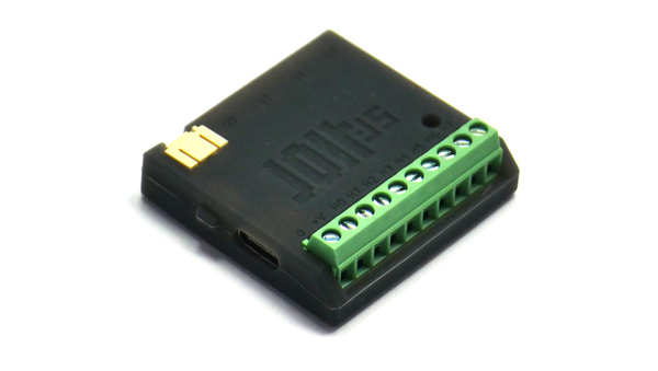
Jolt.js is a programmable Bluetooth Motor Driver board. Control powerful external devices such as lights, motors, solenoids and relays, all from a device that can run for months or years on a battery!
With the Espruino JavaScript interpreter on its internal ARM microcontroller, software can be uploaded, debugged and modified wirelessly from any modern computer or phone, making development of embedded devices significantly easier. Jolt.js has 8 high power outputs, capable of 1A each, as well as 4 Qwiic connectors. It can even control and be controlled by other Bluetooth LE devices.
Just got your Jolt.js? Take a look here!
Contents
- Features
- ⚠️WARNING⚠️
- Powering Jolt.js
- Reverse Voltage Protection
- Power Consumption
- Resetting Jolt.js
- Hard Reset
- Tutorials
- Pinout
- Terminal Block
- Information
- Motor Drivers
- Drive Current
- Wiring up loads
- Stepper Motors
- RGB LED strip
- Individually Addressable LEDs
- Using as Inputs
- Analog Inputs
- Qwiic/Stemma Connectors
- On-board LED and Buttons
- Firmware Updates
- Troubleshooting
- Other Official Espruino Boards
Features
- Bluetooth Low Energy
- Espruino JavaScript interpreter pre-installed
- nRF52840 SoC - 64MHz ARM Cortex M4, 256kB RAM, 1MB Flash
- 8x high power 1A H-bridge outputs on screw terminals
- 4x Qwiic/Stemma connectors (2x analog capable with 500mA FET, 2x with 4x GPIO)
- 2.7v to 18v input range
- Ultra low power (down to 0.008mA) when idle
- LiPo battery connector with inbuilt charger
- USB-C with USB Serial support
- 1x 3mm mounting hole
- 1x Button
- 40mm x 40mm x 12mm with protective silicone case
- PCB Dimensions: 37.2mm x 36mm
⚠️WARNING⚠️
Jolt.js allows you to power things at much higher voltages and currents than normal microcontrollers. If these higher voltages are wired up wrong they can cause sparks, get hot, and will cause electrical damage.
While we have tried to make Jolt.js as hardy as possible, there are limits to how tough we can make it while also allowing it to run off a wide voltage range with a low power consumption.
- Wiring a battery backwards to Jolt.js's terminals will destroy it.
- Powering Jolt.js with more than 18v (even for a split second) will destroy it (18v power tool batteries are more than 18v)
- The Qwiic connectors are only designed for 3.3v, so connections to these should be kept separate from the Terminal block.
We cannot offer warranty for a Jolt.js that has been wired up backwards or powered with too high a voltage
We'd recommend some safety precautions:
- If powering with a battery via the terminal block, add a sensibly sized fuse (ideally 5A maximum).
- Measure the voltage on unknown batteries with a volt meter before you use them with Jolt.js, and ensure they're under 18v and the correct polarity.
- See
Powering Jolt.jsbelow before you attempt to power Jolt.js from anything other than USB or a 3.7v LiPo battery on the JST connector - When developing with Jolt.js, communicate via Bluetooth wherever possible. While Jolt.js can do USB, ensuring your expensive PC isn't physically connected is a great idea just in case there are any loose wires or ground loops.
- ⚠️ Some switch-mode bench power supplies are very badly regulated. While charging up the capacitors inside Jolt.js some can overshoot the selected voltage by over 60% (so 12v becomes 20v for a few milliseconds) and can destroy your Jolt.js. Please use under 12v and 100mA unless you are 100% sure of the quality of your power supply.
Powering Jolt.js
⚠️WARNING⚠️ Jolt.js is rated for 18v maximum voltage. Higher than 18v (even temporarily) will cause damage to the voltage regulator:
- '18v' power tool batteries can be up to 21v when charged and are not suitable
- When driving inductive loads, care must be taken so that Back EMF doesn't push the voltage rail above 18v. Jolt.js contains around 9uF of capacitance between
GND/V+but if driving larger loads or running off 12v or above we'd recommend an additional 100uF 35v electrolytic capacitor (or greater).
Jolt.js can be powered in multiple ways:
- USB-C - USB-C can power your Jolt.js from 5v, with a 1A self-resettable fuse (via a diode)
- This can be disabled by cutting the
USB +solder jumper on the rear of Jolt.js
- This can be disabled by cutting the
- LiPo battery - You can plug a single cell (3.7v) LiPo battery into the JST PH connector on the board. It will power the board via a diode (rated 3A, ~0.35v drop), and will be charged with a LiPo charge circuit (at 100mA) when USB power is applied (at this point Jolt.js will be powered via USB). See
Solder Jumpersbelow for more info on configuring for different battery situations. - Terminal Block - you can attach 2.7 -> 18v directly to the screw terminals on Jolt.js (which are connected directly to the motor driver). We would strongly recommend you attach a fuse between Jolt.js and your battery with a trip current of not much more than you expect to draw from it (eg 5A).
| USB | LiPo | Terminals | Voltage | |
|---|---|---|---|---|
| Y | 4.65v | USB 5v minus 0.35v diode voltage drop | ||
| Y | ~3.3v | LiPo voltage minus 0.35v diode voltage drop | ||
| Y | Y | 4.65v | USB 5v minus 0.35v diode voltage drop, LiPo charged @ 100mA | |
| - | - | Y | ---- | Terminals power motor drivers directly. Note: if USB/LiPo is connected and voltage is higher, they will be used |
As mentioned above, you can change the behaviour by modifying the solder jumpers on the rear of the board:
Solder Jumpers
On the rear of Jolt.js are some pads which can be cut/soldered to change how it can be powered.
Note: these pads are connected to the LiPo/USB/terminals so should not be left bare.
LiPo Pwr(default open) - Jolt.js includes a 3A, 0.35v drop diode from the JST battery connector to the motor drivers/terminals. If you're planning on drawing more than 3A or you want to avoid the voltage drop, you can short this jumper which shorts out the diode.LiPo Chg(default shorted) - Jolt.js includes a 100mA LiPo battery charger which charges a battery on the JST connector. If you don't want charging or are planning on using a multi-cell or non-LiPo battery, cut this jumper so that the battery won't be charged and the charge circuit won't be broken if the voltage is too high.USB Pwr(default shorted) - Jolt.js includes a 3A, 0.35v drop diode from the USB connection (plus a 1A self-resetting fuse) to the motor drivers/terminals. If you're connecting a <4.6v battery to the termnals, or you've shortedLiPo Pwrthen you can cut this jumper to disconnect the diode and stop USB power being used for anything other than LiPo Charging (ifLiPo Chrgis shorted)
To 'open' a shorted solder pad, you need to cut inbetween the two gold pads. ⚠️ Always check with a multimeter to ensure that the two pads really are disconnected if you need them open.
| LiPo Pwr | LiPo Chg | USB Pwr | Notes |
|---|---|---|---|
| OPEN | SHORT | SHORT | Default 3.7v LiPo on JST only, with charge (but 0.35v voltage drop). Uses USB voltage when USB connected. |
| OPEN | SHORT | OPEN | 3.7v LiPo on JST only, with charge (but 0.35v voltage drop). USB only charges battery, but doesn't power Jolt.js |
| SHORT | SHORT | SHORT | 3.7v LiPo on JST only, high power, no voltage drop. Do NOT USE USB with battery connected |
| SHORT | SHORT | OPEN | 3.7v LiPo on JST only, with USB charge (but not using USB voltage) |
| OPEN | OPEN | SHORT | 3->18v battery on JST (but 0.35v voltage drop). Uses USB voltage when USB connected if battery <4.6v |
| SHORT | OPEN | SHORT | 3->18v battery on JST, no voltage drop. Do NOT USE USB with battery connected if battery <4.6v |
| OPEN | OPEN | OPEN | 3->18v battery on JST (but 0.35v voltage drop). USB power unused. |
| SHORT | SHORT | SHORT | DO NOT DO THIS - could break charge circuit |
Note: By JST we mean the JST PH LiPo connector on the rear edge of the board, not the terminal block.
Reverse Voltage Protection
Jolt.js does not have reverse voltage protection - always check the polarity when you're powering Jolt.js. Wiring Jolt.js up to a battery backwards will void the warranty!
- There is a 3A diode across the terminal block inputs, so there is minimal protection if Jolt.js is wired in reverse for a very short time to low current voltage sources. However if you attach Jolt.js to a car battery backwards it'll be destroyed instantly.
- Similarly the JST battery connector has a diode from it (unless
LiPo Pwris shorted), but wiring a battery up to the JST connector in reverse will likely destroy the battery charge circuit.
Power Consumption
All power figures below are with the LCD on:
- No advertising - 0.008mA
- Advertising - 0.06mA
- Connected via BLE - 0.8mA
- Connected via BLE (1 min inactivity, or
NRF.setConnectionInterval(200))- 0.05mA - 1x Motor driver on - 2.7mA
- 2x Motor drivers on - 5.4mA
- 100% CPU usage running JavaScript
- Using
NRF.findDevicesto scan for devices - 12mA
Resetting Jolt.js
Occasionally you may want to hard-reset Jolt.js. To do this you just need to power cycle the board (or you can call E.reboot() from JavaScript)
Resetting Jolt.js this way will not clear out any saved code - see Hard Reset below.
Hard Reset
To clear out all saved code, reset Jolt.js while keeping the button held for around 10 seconds (even while Jolt.js's green LED is active).
Once Jolt.js has stopped flashing LEDs you can release it - this will clear out any previously saved code and bonding data that could have caused problems.
Note: If you release the button when all 3 LEDs are lit (eg the LED is white) then a self-test will be performed. Saved code will not be loaded from flash, but will not be erased from flash either - a subsequent reset will start Espruino up loading the saved code as normal.
Tutorials
First, it's best to check out the Getting Started Guide
There is more information below about using the motor driver and Qwiic connectors.
Tutorials using Jolt.js:
 Jolt.js Motion Activated Lights
") Advanced Debug (SWD)
Advanced Debug (SWD)
 nRF52 Low Level Interface Library
 Jolt.js Talking Clock
 Jolt.js LEGO Control
 Jolt.js Combination Lock
Tutorials using Bluetooth LE:
 Battery Monitor
 BTHome Library
 Bluetooth Characteristic Notifications
 LEGO WeDo 2.0
") LEGO Power Functions Clone Remote Control (Mould King M-0006 / Kaiyu / Bandra / AKOGD / MayD / etc)
LEGO Power Functions Clone Remote Control (Mould King M-0006 / Kaiyu / Bandra / AKOGD / MayD / etc)
") Quick Start (Bluetooth LE)
Quick Start (Bluetooth LE)
 Pixl.js Bluetooth to Ethernet MQTT Bridge
 Bluetooth LE Printers
 Bluetooth LE Emoji Advertising
 Tilt Hydrometer Repeater
 BLE Advertising with Node.js/Python/C#/Android
 Automatic Data Download
 Puck.js to GCP BigQuery & Data Studio
 Stream from Puck.js to AWS IOT Core & SNS Email
") Bluetooth LE UARTs (NUS)
Bluetooth LE UARTs (NUS)
 Bluetooth LE HID Keyboards
 Bluetooth LE Security and Access Control
 Bluetooth LE MIDI
 Web Bluetooth on Linux
 Bluetooth Time Setter
 Using Web Bluetooth with Espruino
 Bluetooth LE and If This Then That
 UART.js Library
 Eddystone Beacons
 Bluetooth LE and Node-RED with MQTT
 Bluetooth Music Controller
 Controlling Bluetooth Lights with Puck.js
 Bluetooth LE HTTP Proxies
 Exercise Machine controlled Video
 BLE Communications
") About Bluetooth LE (BLE)
About Bluetooth LE (BLE)
 Puck.js with SMS control
 Pixl.js SMS Remote Monitoring
 Web IDE on a Raspberry Pi
 Puck.js Bluetooth with the Graphical Editor
 Controlling Other BLE Espruino Devices
 Pixl.js Simple Logger
 Pixl.js Multiplayer Pong Game
 BLE Characteristic Scan
LED BLE Library
Bluefruit LE app interface
BLE Characteristic Scan
LED BLE Library
Bluefruit LE app interface
Tutorials using Bluetooth LE and functionality that may not be part of Jolt.js:
 DIY Smart Meter
 BTHome and Home Assistant Setup
 BTHome Door Sensor for Home Assistant
 Water Level Monitor
 Puck.js Vibration Sensor
 Interfacing to a PC
 Pixl.js Wireless Temperature Display
 Turning an Espruino Puck.js Into a Universal Presentation Clicker
 Controlling Espruino from Tensorflow on the Desktop
 Bookmarklets with Web Bluetooth
 Bangle.js Data Streaming
 Puckmote - Universal Remote Control
 IoT for Kitchen Gardens
 Time Machine Retro-Inspired Smartwatch
 Talos, Keeping You Safe During Your Commute
 Bluetooth Energy Usage Monitor
 Electric Skateboard Controller
 Wooden Bluetooth Remote for Lego Duplo Train
 Puck.js Control from Android using DroidScript
 Ikea Eneby Speaker Controller
 Pixl.js Wireless Weather Station
 Temperature Controlled Night Light with Puck.js
 Infrared Record and Playback with Puck.js
 Door Controlled Light with Puck.js
 Freezer Alarm
There are many more tutorials that may not be specifically for you device but will probably work with some tweaking. Try searching to find what you want.
Pinout
Hover the mouse over a pin function for more information. Clicking in a function will tell you how to use it in Espruino.
- Purple boxes show pins that are used for other functionality on the board. You should avoid using these unless you know that the marked device is not used.
- ! boxes contain extra information about the pin. Hover your mouse over them to see it.
- 3.3v boxes mark pins that are not 5v tolerant (they only take inputs from 0 - 3.3v, not 0 - 5v).
- GND is ground (0v).
- +V is the positive voltage input (not the same as 3.3v!).
- ADC is an Analog to Digital Converter (for reading analog voltages)
Note: Jolt.js has one available I2C, SPI and USART (and infinite software SPI and I2C). Unlike STM32-based Espruino boards, these peripherals can be used on any pin.
Terminal Block
Jolt.js comes with a 10 pin screw terminal block on one side. On it are the high power motor driver outputs, as well as screw terminals for GND and whatever voltage it is being powered from.
From the factory, the terminal blocks are closed. Even though there appears to be a hole, to insert a wire you must unscrew the terminals, insert the wire above the blade in the terminal block, and then screw the terminal block back up.
Information
- There's an API reference here
- Circuit Diagram (Schematic) - PDF, Eagle CAD
- Board Layout - PDF, Eagle CAD
Certifications:
- Jolt.js's radio module has certifications for FCC (USA), CE(EU), TELEC (Japan), SRRC (China), IC (Canada), NCC (Taiwan) and KC (South Korea)
Motor Drivers
Jolt.js has 8 powered outputs, divided between two motor drivers (H0/H1/H2/H3 are on driver 0,H4/H5/H6/H7 are on driver 1). Each output can supply 1A.
When enabled, the 2 motor drivers each draw around 2.7mA, so they are disabled by default and all outputs are then mostly (~2.5 kOhm to GND) open circuit, but are clamped with internal diodes between GND and +V on the terminal block.
Note: On preproduction firmwares there is no "auto" mode and you must manually enable the motor drivers with Jolt.setDriverMode(driverNumber,mode)
By default, the motor drivers are in "auto" mode. Setting any pin in a bank (H0/H1/H2/H3 or H4/H5/H6/H7) to an output will enable the entire bank. For instance H0.set() will enable motor driver 0
and will set H0 to VCC, but H1, H2 and H3 will then be pulled to GND. To disable the motor driver, H0 must be set back to an input (using H0.read() is the easiest but pinMode(H0,"input") or H0.mode("input") will
work too if you want to be explicit about setting the pin state).
To enable a motor driver manually, use Jolt.setDriverMode(driverNumber,mode), and then set the pin to the value you want. For example:
Jolt.setDriverMode(0,true); // enables H0..H3
H0.set(); // H0 now outputs a high voltage
setTimeout(function() {
  Jolt.setDriverMode(0,false); // disables H0..H3
}, 1000);

Jolt.setDriverMode(1,true); // enables H4..H7
H4.set(); // H4 now outputs a high voltage
setTimeout(function() {
  Jolt.setDriverMode(0,false); // disables H4..H7
}, 1000);
The argument to Jolt.setDriverMode can be one of several different values (see the reference)
but the most useful values are true (enable in the default mode where all pins are pulled either high or low) or false (disables, making all pins open circuit).
Drive Current
The motor drivers can supply 1A per output, however they will cut out to protect themselves if they detect too much current flowing or that they are getting too hot.
When this happens with something physical like a motor you may hear a high-pitched whine as the motor driver turns itself on and off repeatedly.
You may well find that a motor that refuses to run at a high voltage (with a whine) will run perfectly fine at a lower voltage as the current required is then low enough.
If you need to control a larger load, consider using Jolt.js to power a relay which then powers your load. Automotive relays are commonly available, will supply large amounts of current, and can easily be connected to Jolt.js's powered outputs.
If you just need a bit more power, you can always join multiple outputs together external to Jolt.js and set them at once with digitalWrite([H0,H1], true). Just ensure you don't accidentally set them to different values in software!
Note: If you attach an ammeter right across an output it won't read 1A, as the motor driver will detect a current draw higher than 1A and will turn off immediately.
Wiring up loads
Where possible, loads should be connected between GND and the motor driver. This ensures that when the motor driver is off, the ~2.5kOhm internal resistance of the motor driver is not causing excess power draw.
If you do have to attach loads between +V and the motor driver, consider powering the positive side of the load from one of the motor driver outputs too so you can turn it off when you don't need it.
Stepper Motors
Jolt.js contains a Stepper class for easy control of stepper motors. For instance you can wire a 5 wire stepper motor between GND and H0..H3, you can use the following code:
Jolt.setDriverMode(0,true); // enables H0..H3
var s = new Stepper({pins : [H0,H1,H2,H3], freq : 100 });
// step 1000 steps...
s.moveTo(1000, {turnOff:true}).then(() => {
  print("Done!");
});
RGB LED strip
Jolt.js can easily drive RGB strip where there are separate wires for red, green and blue.
This LED strip is often 'common-anode', meaning there might be a 12v wire, then R, G and B wires which need to be pulled down to ground to turn the LEDs on.
While you can connect the 12v wire direct to the +V pin on the terminal block, when the motor
driver is off there is a small (2.5kOhm to GND) resistance on the motor driver pins which can
cause the LEDs to light slightly (as well as some extra power draw).
To avoid this we'd recommend connecting the 12v wire to the motor drivers as well, so that everything can be turned off at the same time.
Jolt.setDriverMode(0,true);
H3.set(); // enable LEDs
function timer() {
  var c = E.HSBtoRGB(getTime()/3,1,1,true);
  analogWrite(H0, 1-(c[0]/256));
  analogWrite(H1, 1-(c[1]/256));
  analogWrite(H2, 1-(c[2]/256));
}
setInterval(timer,20);
Individually Addressable LEDs
Espruino supports sending the signals needed for WS2811/WS2812/WS2812B/APA104/APA106/SK6812 Individually Addressable LEDs (collectively called Neopixels by Adafruit) using the Neopixel library.
For some types of LED, the 3.3v signals from the Qwiic connectors are not high enough voltage to reliably drive the strip directly, but on Jolt.js you can just use the motor drivers to get the required voltage.
Even when off, the LEDs can draw a significant amount of power (up to 1mA per LED) so if you're planning on having the LEDs off for any period of time and running off a battery, consider connecting the 5v supply wire to Jolt.js's motor drivers as well as the data wire. You can then turn off the LEDs completely and go back to drawing microamps.
For example if you connect 5v to H0 and the data line to H1:
Jolt.setDriverMode(0,true);
H0.set(); // turn on the LEDs
var rgb = new Uint24Array(20); // for 20 LEDs
for (var i in rgb)
  rgb[i] = E.HSBtoRGB(i/10,1,1,24); // fill with rainbow colours
require("neopixel").write(H1, rgb); // send to the LEDs
Using as Inputs
On the terminal block, pins H0, H2, H4 and H6 are connected via
potential dividers to analog inputs and so can be read with
analogRead(H0) or H0.analog() (see below).
However, when doing a digital read (eg H0.read()) the value that's read
is what is on the pin connected to the motor driver, so can not be used
directly as an input. You can get around this by accessing the
analog pins directly:
H0->D4H2->D5H4->D30H6->D28
However because of the potential divider, for the input to register as a logic 1 the
voltage on it must be above 10v.
To work around this Espruino 2v25 includes E.setComparator which allows you to be notified when the input rises above or drops below some multiple of 1.37v.
E.setComparator(H0, 1.37); // compare with 1.37v
E.on("comparator", e => {
  print(e); // 1 for up, or -1 for down
});
Note: There is only one comparator so only one pin can be monitored at once.
Analog Inputs
Jolt.js has 8 analog inputs in total:
- 2 are on Qwiic connector
Q0SDA/SCLpins (returning a value of 0..1 for 0 -> 3.3v) - 2 are on Qwiic connector
Q1SDA/SCLpins (returning a value of 0..1 for 0 -> 3.3v) - 4 are connected via potential dividers to motor driver pins
H0,H2,H4andH6(returning a value in volts). These can be used without the motor driver enabled.
Qwiic/Stemma Connectors
Jolt.js has 4 Qwiic/Stemma compatible connectors. Each variable (Jolt.Q0/etc) is an instance of the Qwiic class and contains at minimum sda and scl fields
which correspond to the Qwiic pins.
You can use Jolt.Q0.setPower(1) to set power on the connector (see below) or Jolt.Q0.i2c to directly access an I2C Instance
For instance if you wish to control a SSD1306 OLED from the Q0 Qwiic connector you could do:
Jolt.Q0.setPower(1);
var g = require("SSD1306").connect(Jolt.Q0.i2c, function(){
  g.drawString("Hello World!",2,2);
  g.flip();
}, { height : 16 });
The rear of Jolt.js is marked as follows:
| Marking | Pin |
|---|---|
| 0 | GND |
| + | VCC (3.3v) |
| D | SDA |
| C | SCL |
Q0 and Q1
These have two GPIO connected to sda and scl, and have their power controlled by a 500mA FET which switches GND. To turn the connector on run Jolt.Q0.setPower(1), or use Jolt.Q0.fet to directly access the pin connected to the FET.
The sda and scl pins on these ports are also analog inputs - use analogRead(Jolt.Q0.sda)/etc
Q2 and Q3
All 4 pins are connected to Jolt.js's GPIO (including those usually used for power). As such only around 8mA of power can be supplied to any connected device.
Jolt.Q2.setPower(1) will set the GPIOs for GND and VCC such that whatever is connected to Q2 is turned on. These contain gnd and vcc fields which reference the pins connected to GND and VCC on the Qwiic connector.
Checking battery voltage
All Jolt.js's analog pins are used for GPIO so it doesn't have a built-in method of detecting the battery voltage. You have two options:
E.getAnalogVRef()will return the voltage on the microcontroller, which is powered by a 3.3v voltage regulator. If the voltage drops below 3.3v then you know that the power source is getting close to or has dropped below 3.3v too. For Lithium ion batteries, a voltage of 3.3v means the battery is about 90% discharged.- You can use the motor driver outputs that are capable of analog input (
H0,H2,H4andH6) - just turn one on and measure the voltage on it (you just need to ensure it's not connected to anything that you don't want turned on!). For example:
function getBatteryVoltage() {
  Jolt.setDriverMode(0,true);
  H0.set();
  return new Promise(resolve => {
    setTimeout(function() {
      let voltage = H0.analog();
      H0.reset();
      Jolt.setDriverMode(0,false);
      resolve(voltage);
    }, 50);
  });
}

getBatteryVoltage().then(print);
On-board LED and Buttons
LED
Jolt.js has 3 programmable LEDs, controllable via the LED or LED1 (red), LED2 (green) and LED3 (blue) variables.
digitalWrite(LED,1),LED.write(1)orLED.set()turns the red LED ondigitalWrite(LED,0),LED.write(0)orLED.reset()turns the red LED off
Buttons
There is 1 button on Jolt.js, accessible as BTN or BTN1.
- You can access a button's state with
digitalRead(BTN1)orBTN1.read()(the two commands are identical). - Polling to get the button state wastes power, so it's better to use
setWatchto call a function whenever the button changes state:
setWatch(function() {
  console.log("Pressed");
}, BTN, {edge:"rising", debounce:50, repeat:true});
NFC - Near Field Communications
Note: as of the current 2v21 firmware build, NFC functionality is not enabled in software.
NFC hardware is available on Jolt.js, however it requires you to wire up an antenna, and to solder tuning capacitors to the two capacitor pads on the rear of the board next to the screw hole such that the antenna resonates at 13.56 MHz.
Firmware Updates
Please see the Firmware Update page for detailed instructions.
Troubleshooting
For more answers please check out the Bluetooth Troubleshooting or General Troubleshooting pages.
Other Official Espruino Boards


This page is auto-generated from GitHub. If you see any mistakes or have suggestions, please let us know.